Torque explained
With all gear hubs the axle tries to rotate whilst cycling. When cycling in a reduction gear, the axle attempts to rotate backwards. When cycling in an increasing gear, the axle attempts to rotate forwards. The force with which the axle tries to turn is refered to as torque. The amount of torque depends upon the force applied on the pedals and the gear selected. This torque must be anchored by some means to the frame in order to create forward drive.
On the simple three-speed hubs a flat sided axle is sufficient to secure the torque within the dropout. High performance internal gear hubs such as the Rohloff SPEEDHUB 500/14 require a considerably stronger torque anchoring method due to the wide range of gear ratios.
The amount of torque produced is shown in the table below.
Depending on the type of frame one of three options can be used to secure the torque:
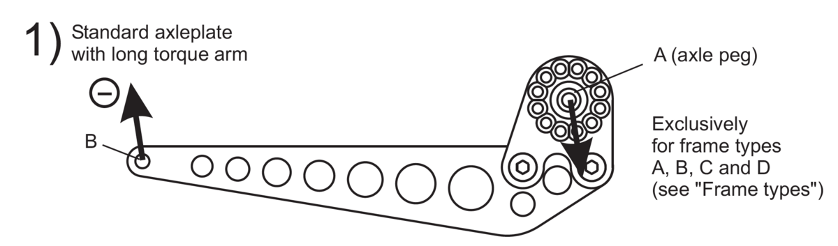
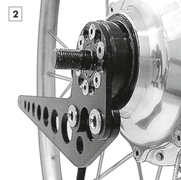
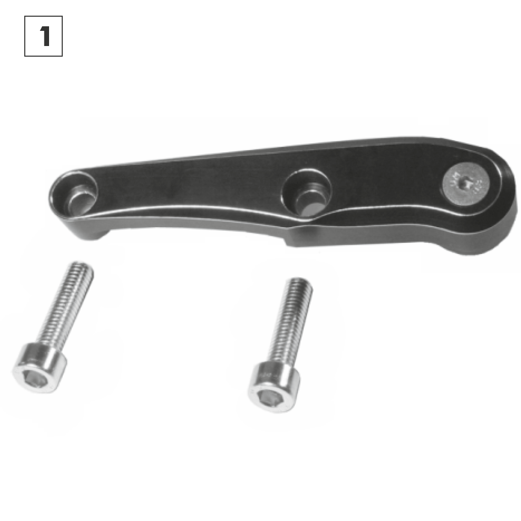
- Standard axleplate with long torque arm
- OEM axleplate
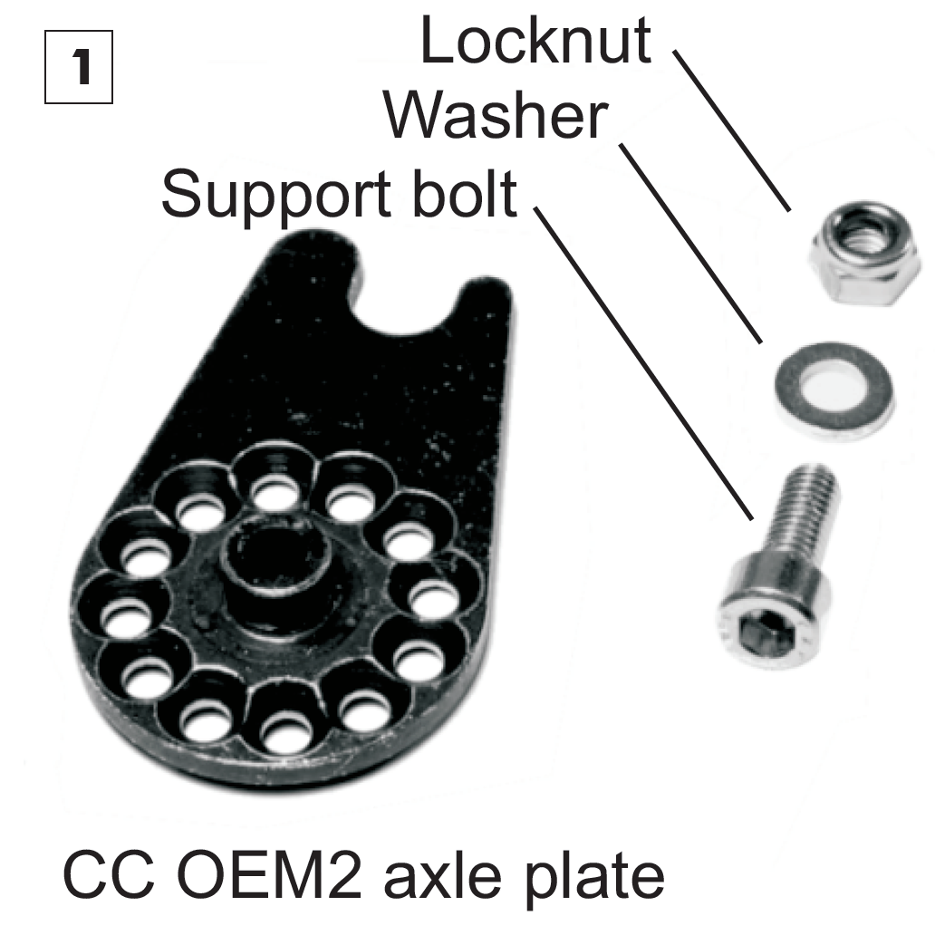
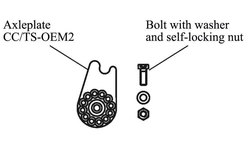
- OEM2 axleplate
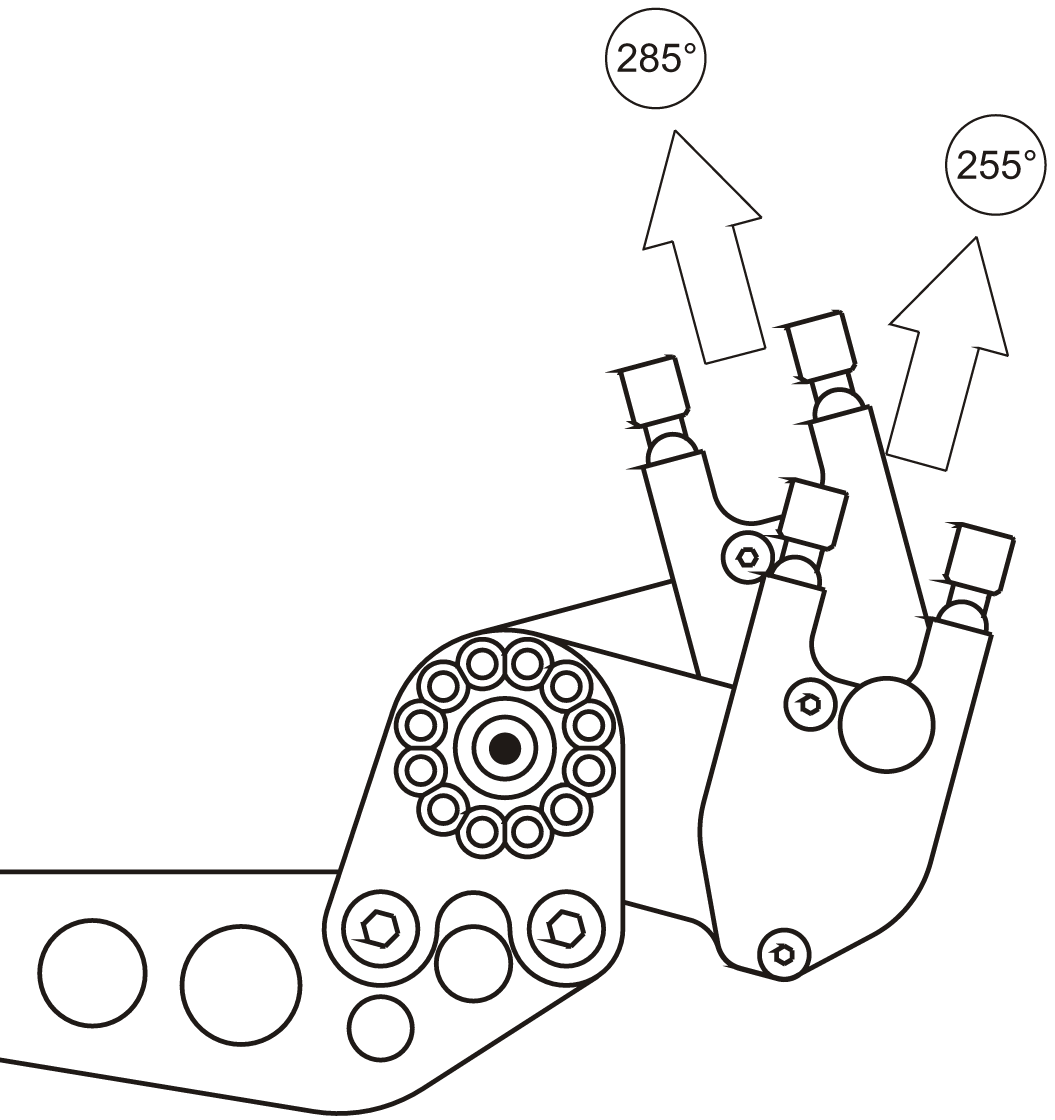
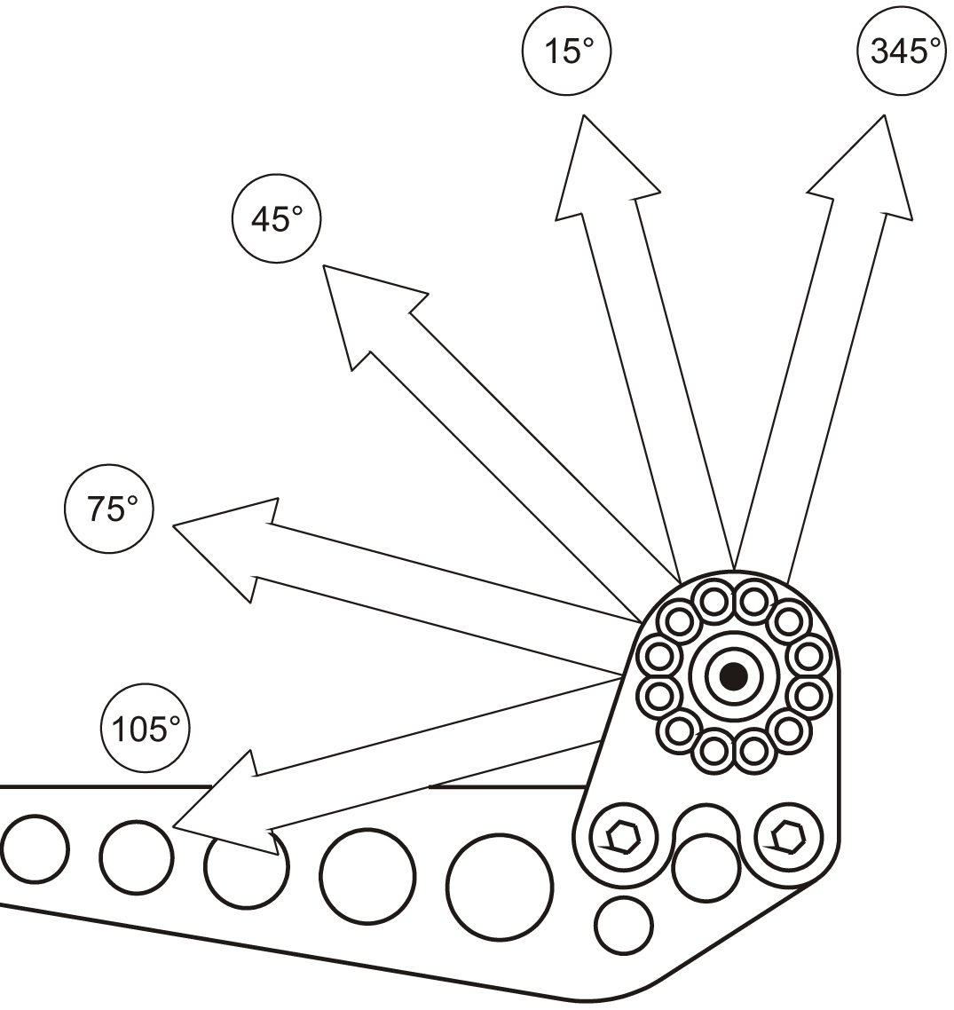
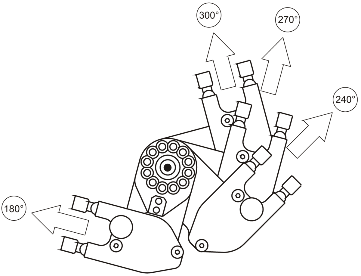
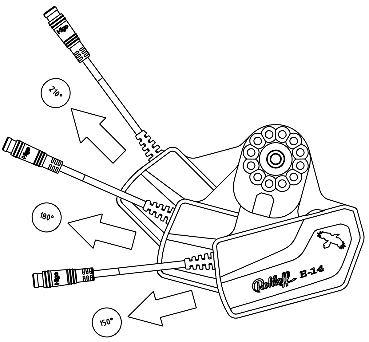
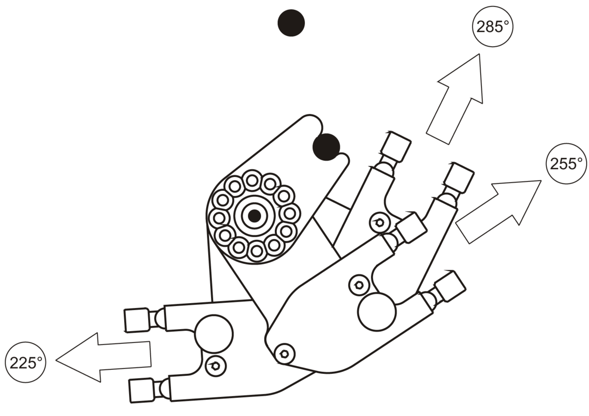
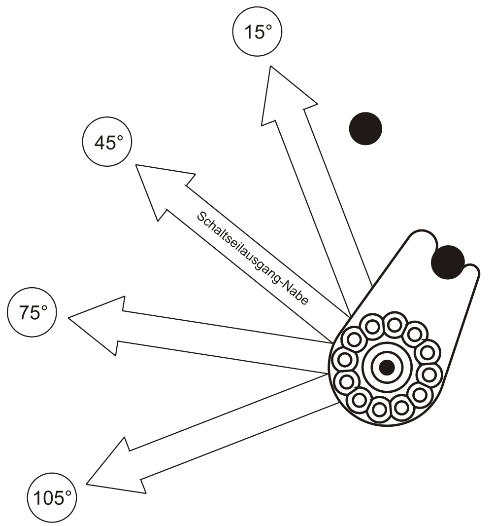
All three anchoring options ensure the axleplate is secured to the frame in two positions to prevents the axle from rotating. The first point A is the axle peg that is secured to the left side dropout. This is the same for all three options. The difference between the three options is point B. The hole pattern on the axleplates allow for individual adjustment of the gear mechs in steps of 30°, so that nearly every frame type can receive an optimum cable routing.
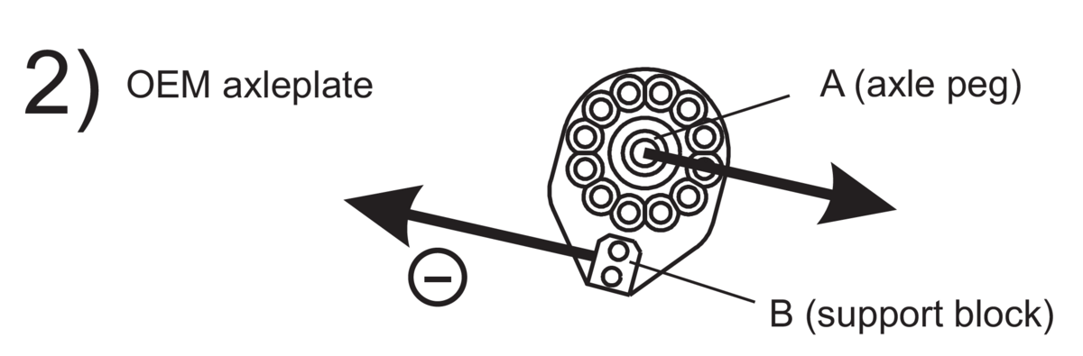
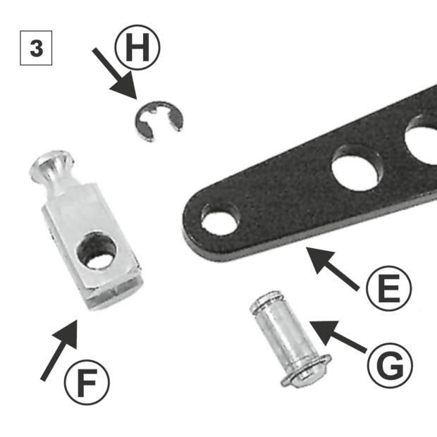
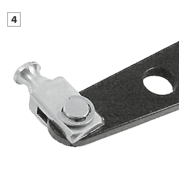
The mounting of hubs with an OEM axle plate is only possible on frames fitted with Rohloff OEM dropouts. The OEM axleplate sits in the dropout slot of the OEM dropout. The axle peg A slides in first followed by the support block B into the same slot. The dropout itself prevents these two parts from turning. When removing the wheel, the two parts fall out the dropout together once the axle has been loosened.
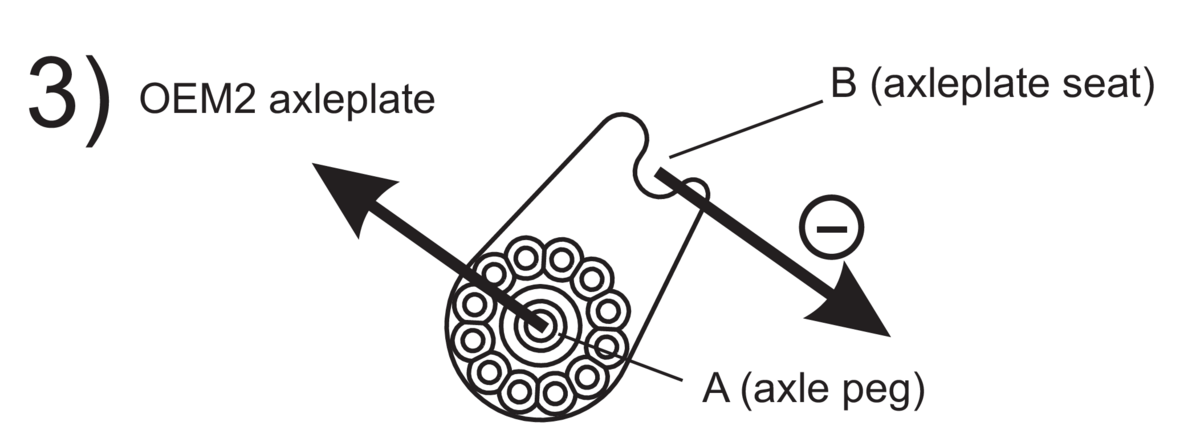
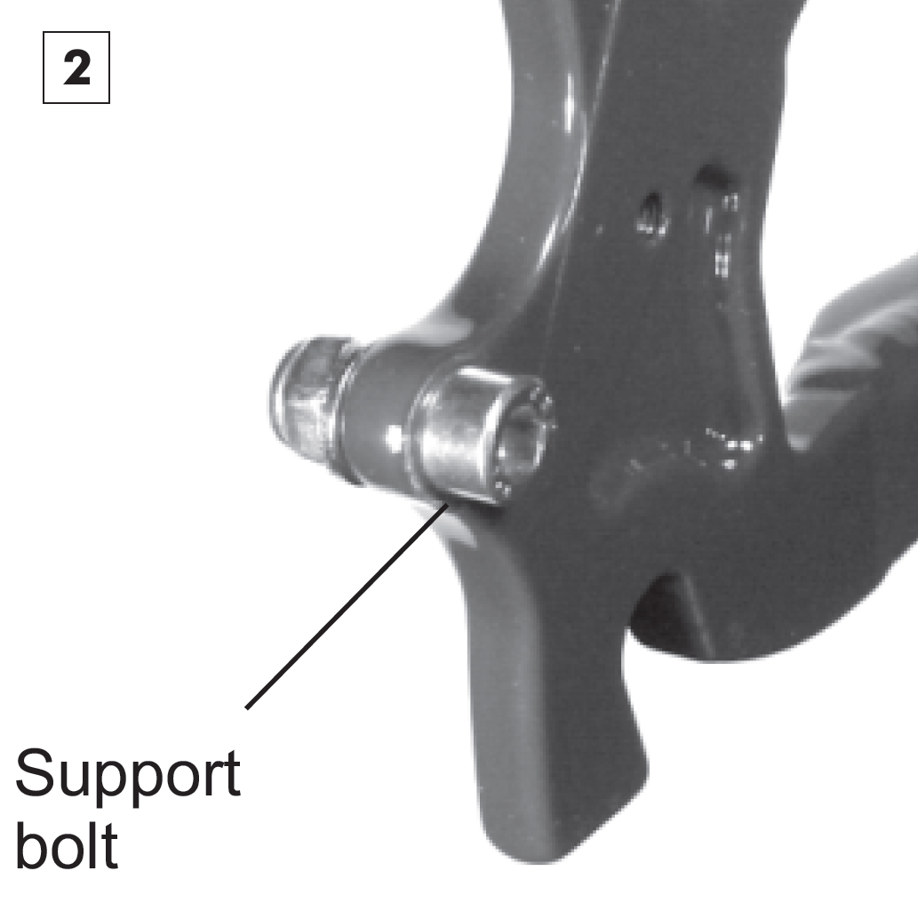
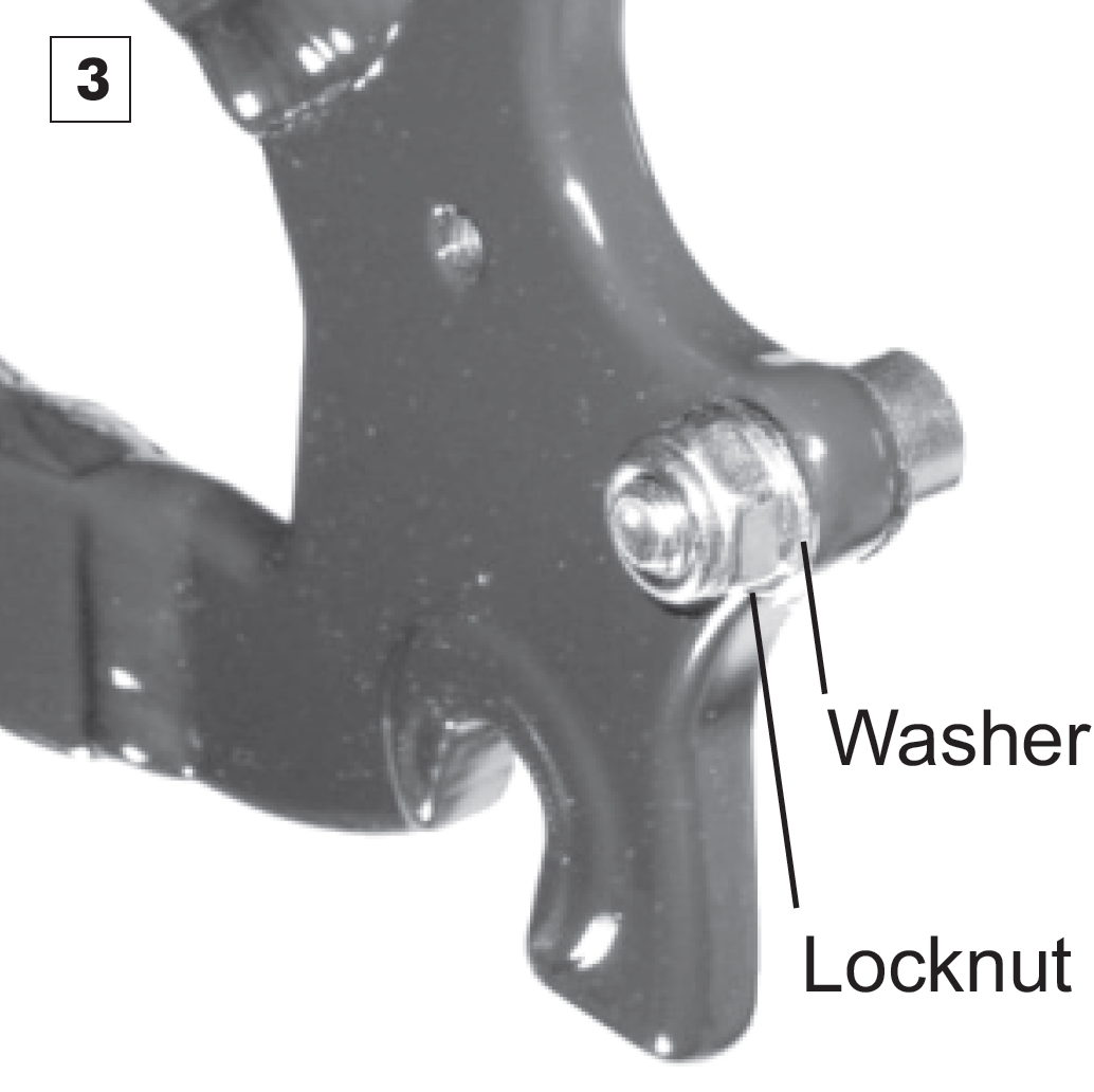
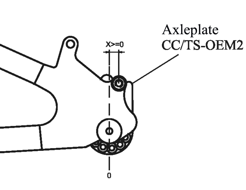
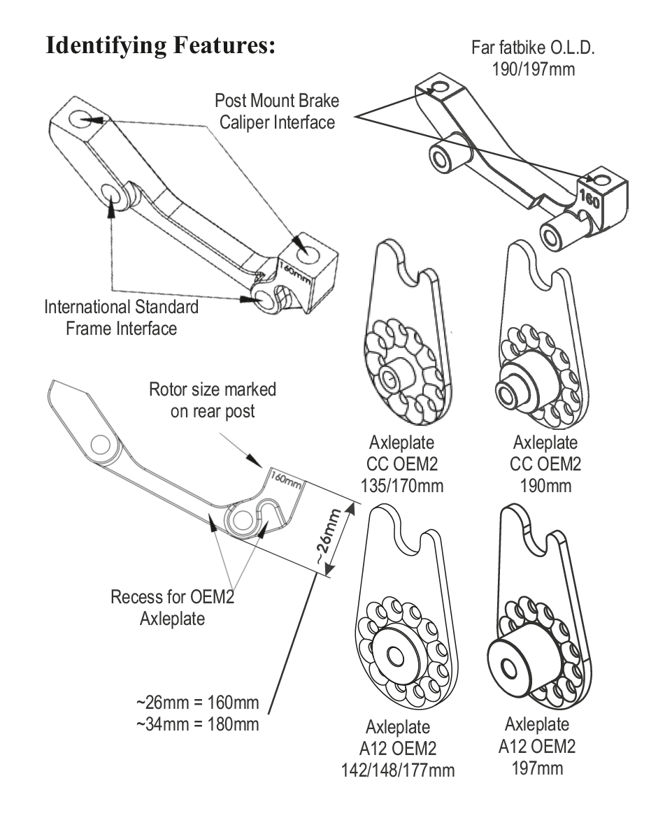
Mounting the SPEEDHUB 500/14 using an OEM2 axleplate is only permitted on frames with international standard (IS1999) disc brake mounts. The OEM2 axleplate sits with its axle peg A in the dropout. The axleplate seat B secures itself around the supporting peg of the Rohloff SPEEDBONE or MonkeyBone (when mounted on a bike with disc brakes) or around the support bolt fastened through the lower brake caliper mounting hole (when mounted on a bike with rim brakes). When removing the wheel, the axleplate falls away from the support bolt/Rohloff SPEEDBONE / MonkeyBone and out of the dropout once the axle is loosened..
Table: Amount of torque
| Gear | 1 | 2 | 3 | 4 | 5 | 6 | 7 | 8 | 9 | 10 | 11 | 12 | 13 | 14 |
|---|---|---|---|---|---|---|---|---|---|---|---|---|---|---|
| % | 98 | 82 | 68 | 55 | 44 | 34 | 25 | 18 | 11 | 5 | 5 | 9 | 12 | |
| backward | ✘ | ✘ | ✘ | ✘ | ✘ | ✘ | ✘ | ✘ | ✘ | ✘ | ||||
| forward | ✘ | ✘ | ✘ |
Long torque arm
OEM mounting

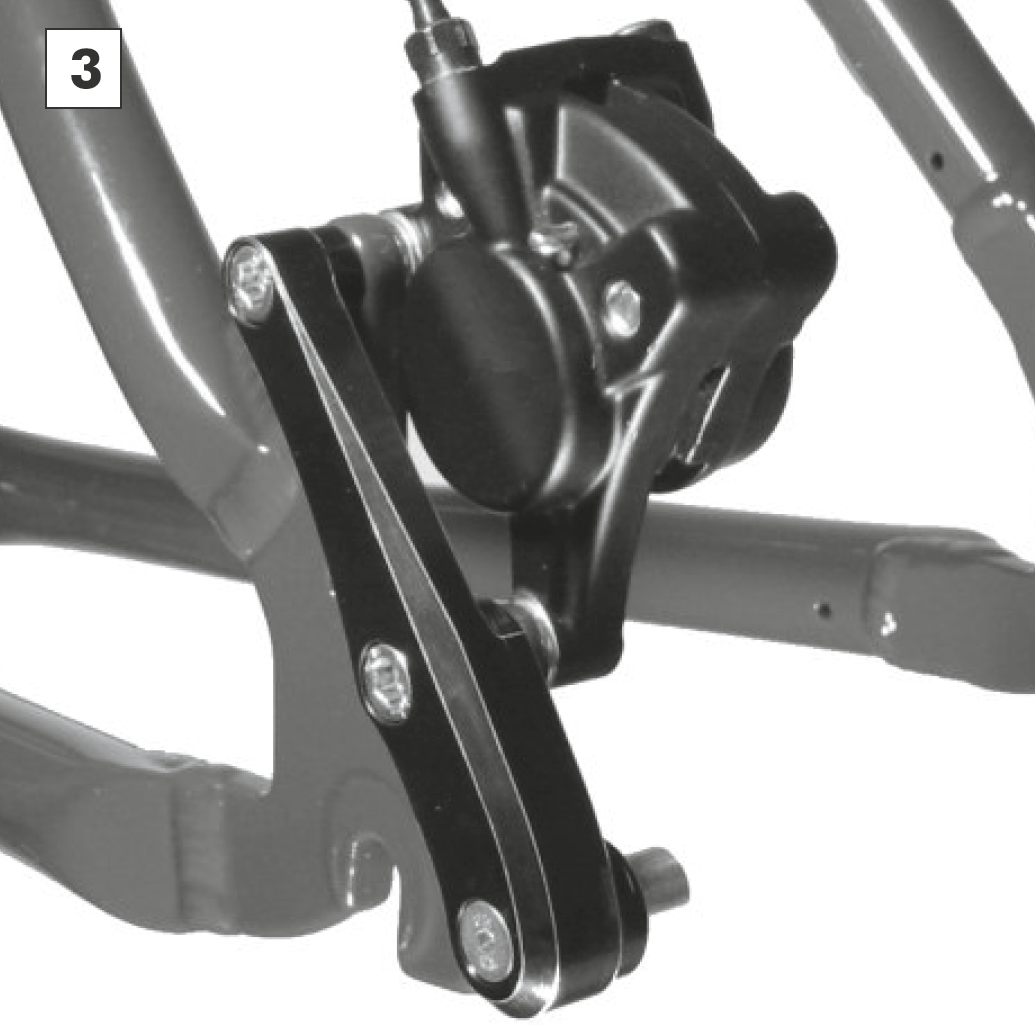
OEM2 mounting
OEM2 mounting with a support bolt
The OEM2 axle plate can be used in two versions with a support screw:
- The frame has a disc brake mount, but no disc brake is installed. Use M6 screw.
- The frame has an M5 luggage carrier thread and the distance to the center of the axle is 39.9 mm. Use OEM2 adapter with M5 screw.
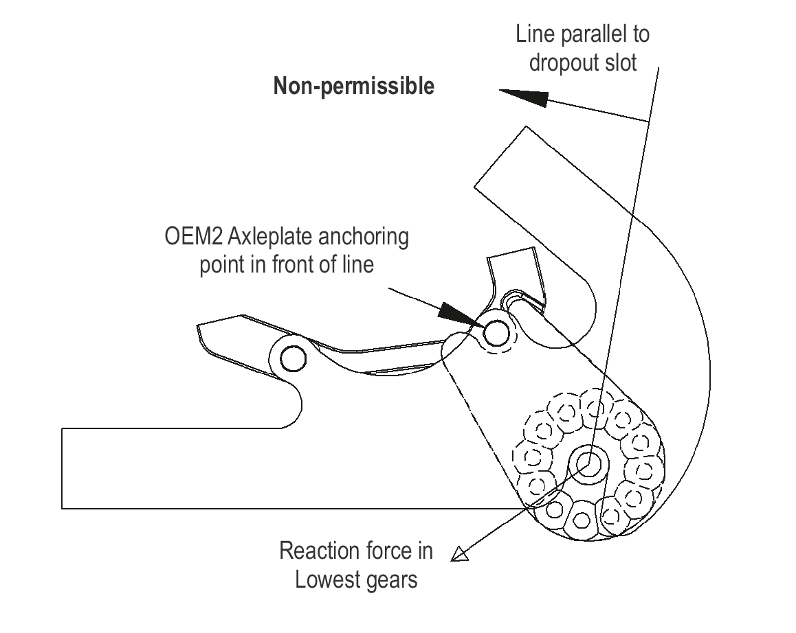
Both versions have in common the position behind the imaginary line through the axle slot. In addition, both need the distance to the center of the axle of 39.9 mm.
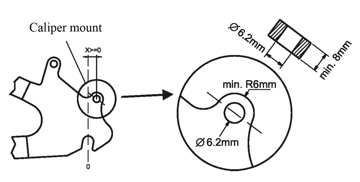
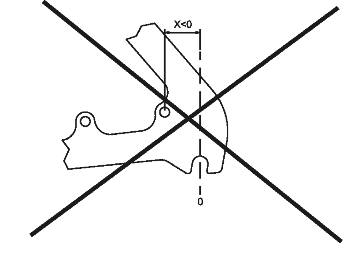

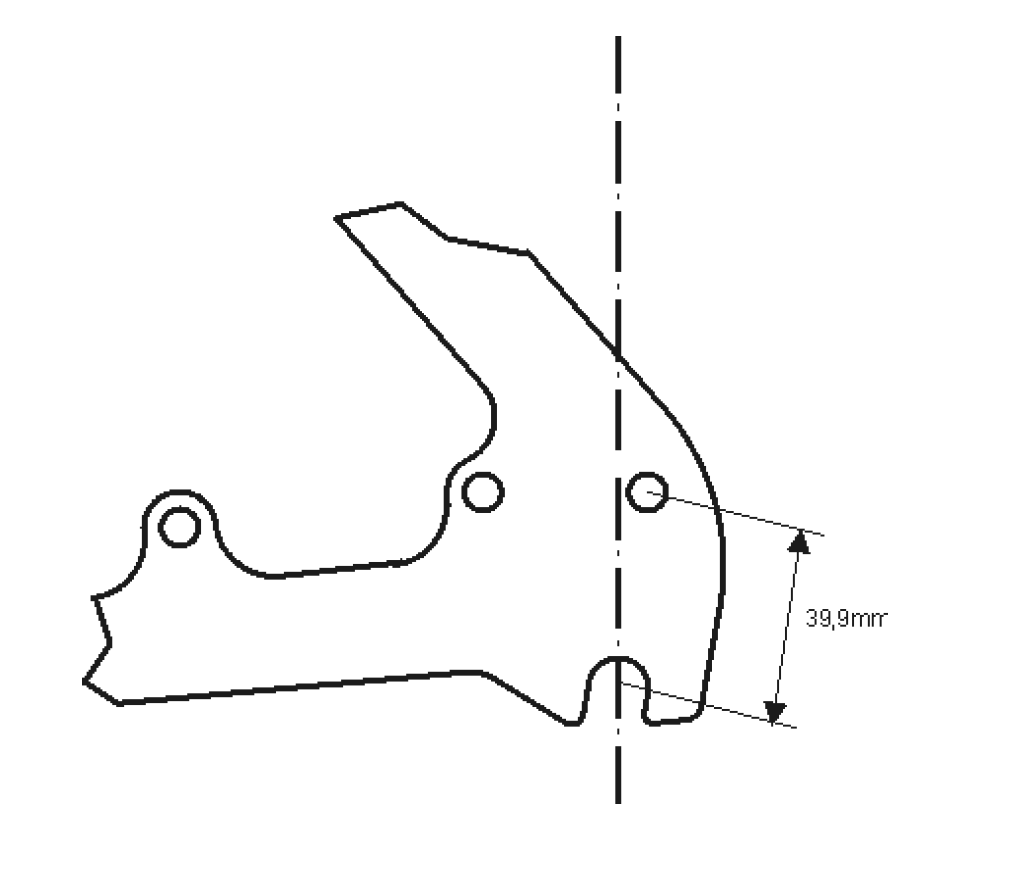
The OEM2 axle plate can also be used when an additional hole is positioned in the dropout behind a vertical line through the axle. This hole must accept an M6 bolt or an M5 bolt in combination with our M5-OEM2 adapter (Article #8552).
Ideally, a drilled & tapped luggage/fender mount hole can be located in the correct position (39,9mm) from the axle center and thus ensuring each frame is SPEEDHUB compatible using Art.#8552, even if not primarily sold with the SPEEDHUB option.

Adapter OEM2 for M5 screw (Article No. 8552)
See also axle plate accessories in our B2B shop.
Important: An M5 cylinder head is only 8 mm in diameter, therefore an M5 screw must not be used without the OEM2 adapter with a diameter of 10 mm (Article No. 8552).
Attention: The combination of M5 adapter (Art. No. 8552) with M5 screw is not approved for use on a tandem or e-bike (max. > 250W nominal power / max. > 800W peak power).
OEM2 mounting using a SPEEDBONE
The Rohloff SPEEDBONE is mounted from the outer side of the frame and secured through the disc brake mounts (IS2000) into the brake caliper (paying attention to the brake manufacturers tightening torques). The original caliper securing bolts will be too short to mount through the Rohloff SPEEDBONE and should, therefore, be replaced by the long Rohloff SPEEDBONE securing bolts.


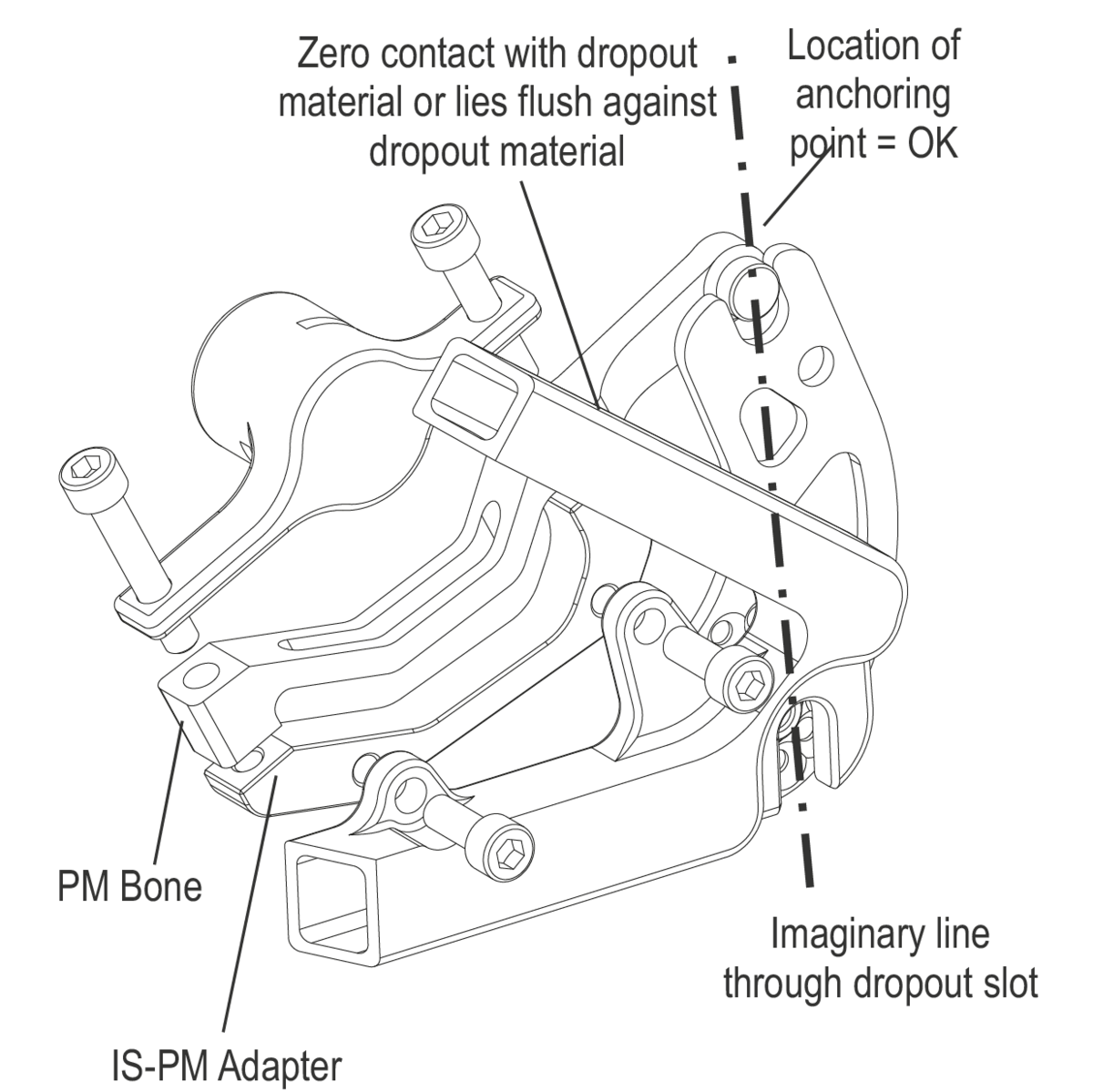
OEM2 mounting using a MonkeyBone
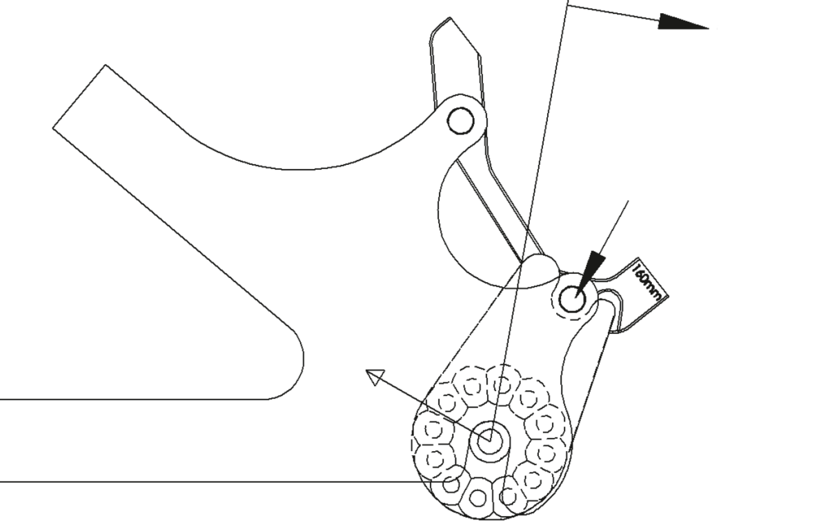
Monkey Bone IS-PM Adapter for O.L.D. 135/142/148/170/177mm
(160mm = Art. #8553) (180mm = Art. #8554)
Monkey Bone IS-PM Adapter for Fatbike O.L.D. 190/197mm
(160mm = Art. #8553-10) (180mm = Art. #8554-10)
The Monkey Bone offers a simple method of anchoring the axle of the Rohloff SPEEDHUB 500/14 to a frame through the disc brake mount. In order to use the Monkey Bone, your SPEEDHUB 500/14 will need an OEM2 axleplate, your frame must have an International Standard disc brake interface, and your disc brake caliper must have a Postmount interface. The Monkey Bone is not compatible with IS direct-mount disc brake calipers or frames with Postmount disc brake interface.
Required Tools
- 5mm Allen wrench
- Torque wrench
- T20 Torx wrench
Required Parts
- Frame with IS51 disc caliper mount interface
- Disc brake caliper with Postmount interface
- Rohloff SPEEDHUB 500/15 with OEM2 axleplate
- Monkey Bone/Monkey Bone-10
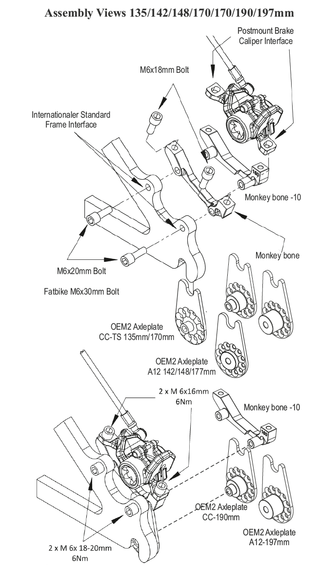
- 2x M6x16mm bolts (sold separately; typically included with disc brake caliper)
- 2x M6x18-20mm bolts (sold separately; typically included with disc brake caliper)
- 2x M6x30mm bolts (included with Art. #8553-10 and Art. #8554-10)
Installation Instructions
- Ensure that you have the Monkey Bone that is appropriate for your disc rotor diameter (160mm or 180mm; 203mm rotors can be used with 180mm Monkey Bone and spacers (sold separately).
- Attach the Monkey Bone to the frame using two M6x18-20 bolts. Ensure that slot for OEM2 axleplate faces the dropout. Tighten bolts to a torque of 6Nm/51 in-lbs.
- Connect disc brake caliper to Monkey Bone using two M6x16 bolts (for Fatbike M6 x 30mm). Leave bolts loose enough that caliper can slide side to side.
- Install wheel into dropout taking care to align slot in end of OEM2 axleplate with cutout in Monkey Bone and disc rotor between brake pads.
- Check position of EX shift arm with OEM2 axleplate engaged with slot in Monkey Bone; reposition axleplate as needed for desired cable routing using T20 Torx wrench (see Rohloff Owners Manual). Tighten axleplate screws to a torque of 3Nm/25 in-lbs.
- Fully seat axle in dropout before tightening quickrelease lever or axle nuts. Threaded axle nut torque: 30 Nm/310 in-lbs; Pitlock or bolt-on skewer torque: 7 Nm/60 in-lbs.
- Follow brake manufacturer’s recommendation for setting brake caliper position. Tighten brake caliper bolts to a torque of 6Nm/51 in-lbs.

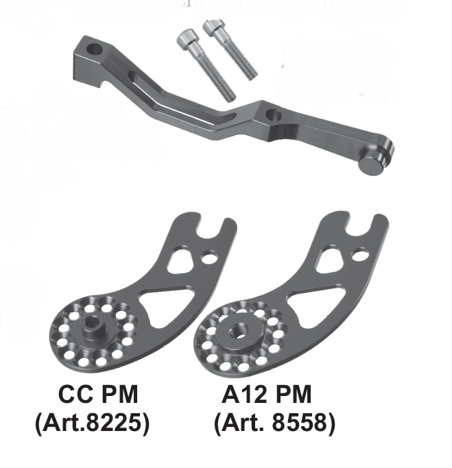
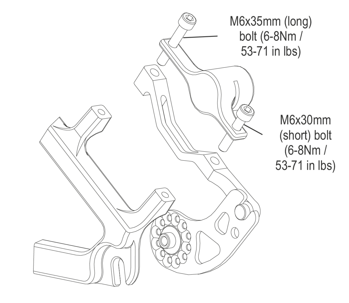
PM Bone Mounting
PM Bone (Art.#8555)
PM axleplate (CC PM =Art.#8225), A12 PM (Art.#8558)
The Rohloff PM Axleplate in combination with the PM Bone offers an alternative method of anchoring the hub torque to frames with a 135mm, 142mm, 148mm, 170mm or 177mm spacing. The PM Axleplate/PM Bone combination is recommended when mounting a SPEEDHUB in all frames with an integrated Postmount direct calliper mount. The threaded holes of the direct calliper mount will be used to secure the PM Bone.
Three different mounting options are available:
- Mounting to frames where the (PM) brake caliper mount is located on the seat-stay.
- Mounting to frames where the (PM) brake caliper mount is located on the chain-stay.
- Mounting on frames where an International Standard (IS) brake caliper mount is located on the Chainstay.
Possible combinations:
PM direct 140mm = Not compatible!
PM direct 160mm = 180mm rotor required!
PM direct 180mm = 203mm rotor required!
PM direct 203mm = Not compatible!

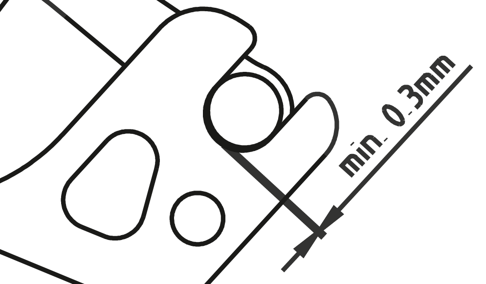
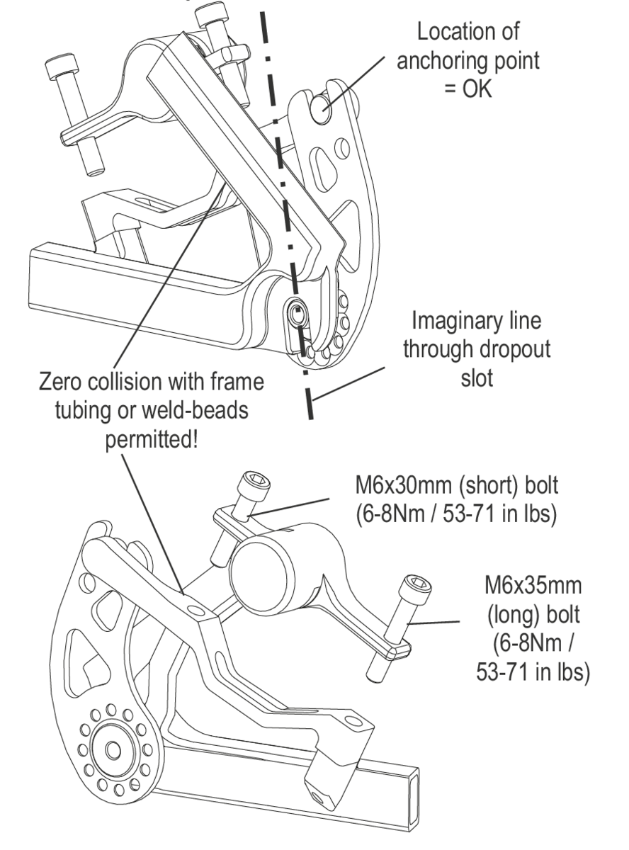
PM Bone - Mounting preconditions
The axle area of the Rohloff PM Axleplate must lie flush against the dropout material.
The axleplate may under no circumstances collide with weld-beads or proud standing frame tubes.
Safe use of the PM Bone/PM axleplate is only possible if these two preconditions are satisfied.

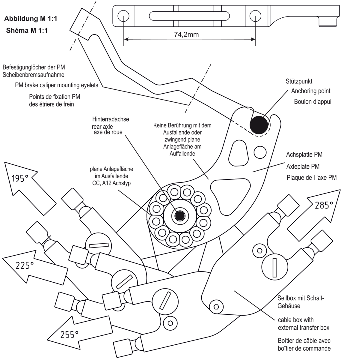
Drawing scale 1:1
Download a PDF with a 1:1 scale drawing to aid the installation, by clicking on the button below. Print the PDF in original size:
Method:
- Hold the drawing against the left-hand side of the bicycle frame. Align the rear axle of the drawing, with the position of the rear axle on the frame.
- Rotate drawing until the PM brake caliper mounting eyelets are located directly behind those of the drawing.
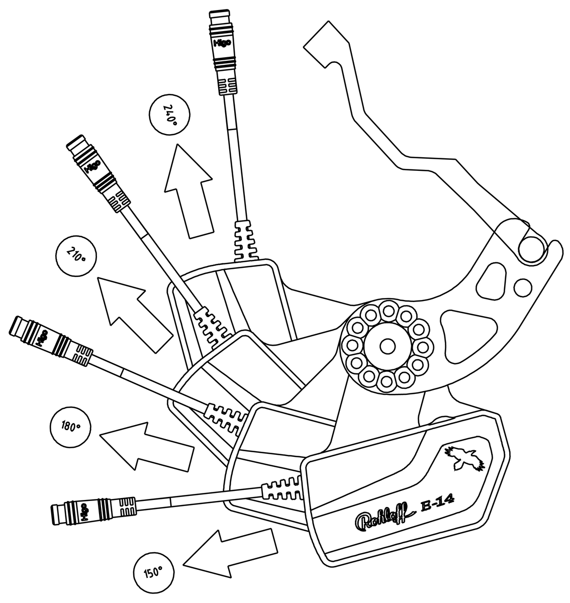
- Position the cable box in such a manner that it aligns with the corresponding angles of the drawing, to create the cleanest, most direct cable routing possible.
- Fasten the axleplate to the SPEEDHUB in this position, using the 5x TX20 axleplate screws (3Nm).
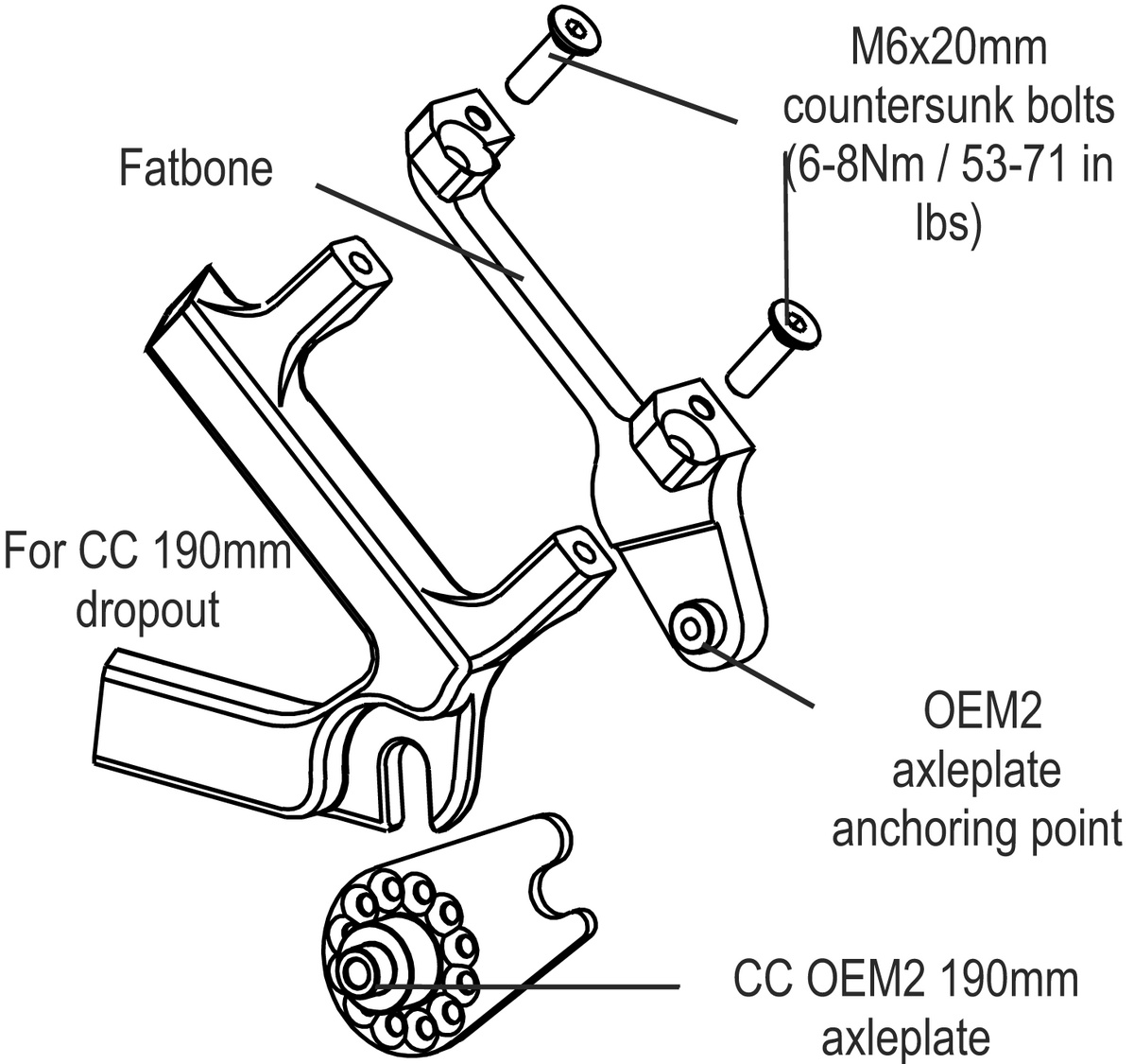
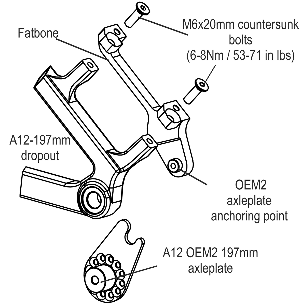
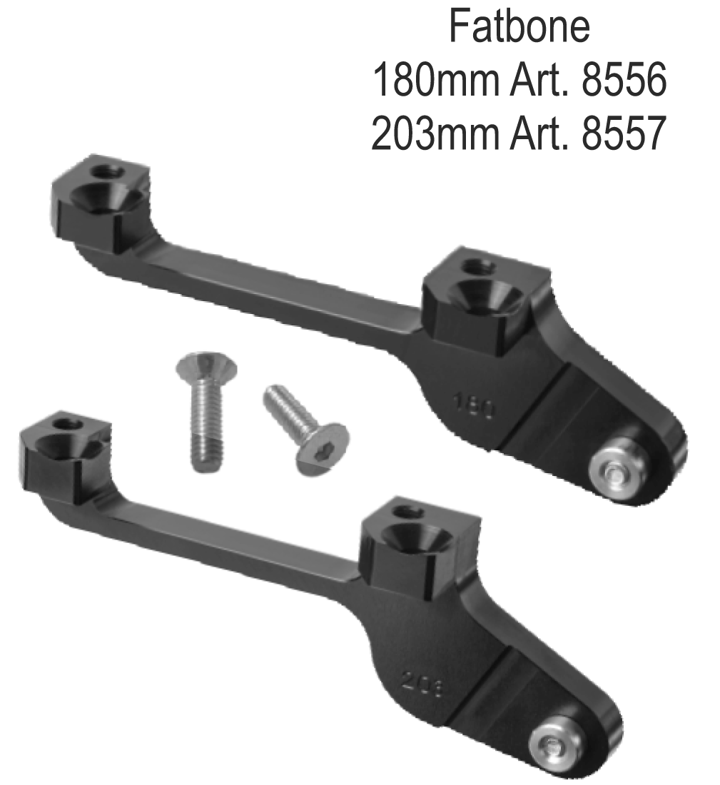
Fatbone Mounting
Fatbone (Art. #8556 + Art. #8557)
Adapter for torque support on 190mm and 197mm fat bikes
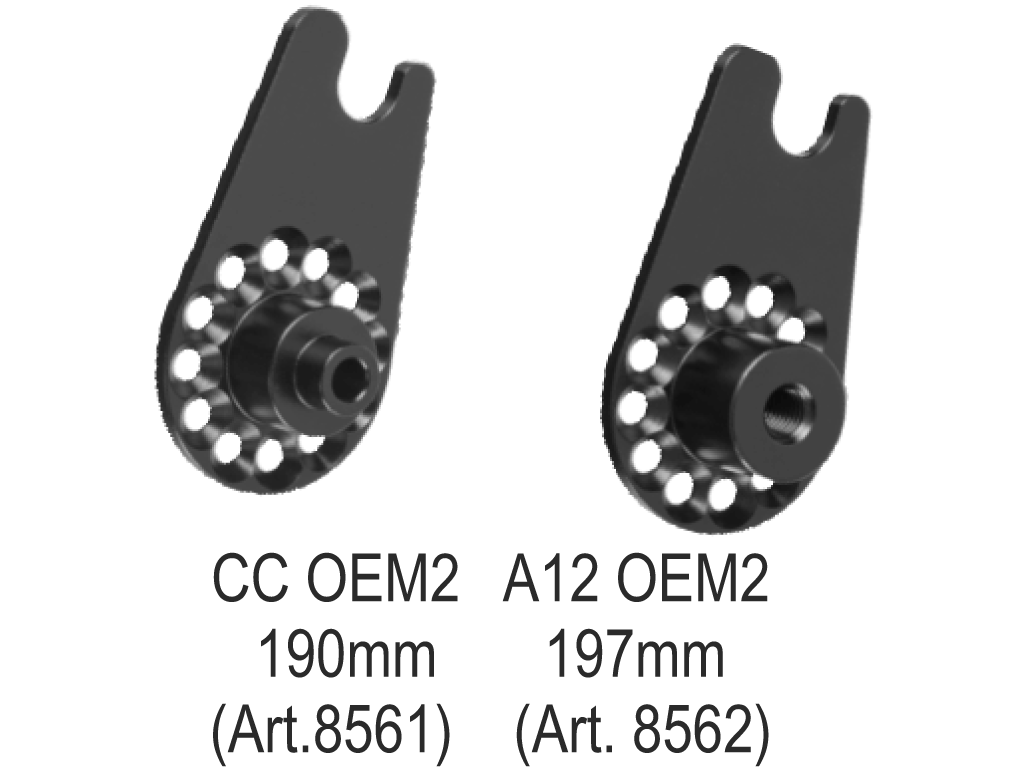
The Rohloff Fatbone enables an OEM2 axleplate (CC-OEM2-190 or A12-OEM2-197) to be used in order to anchor the output torque of a SPEEDHUB unit to a 190mm or 197mm spaced bicycle frame using either a 160mm or 180mm Postmount direct mount brake.
The mounting points of a Postmount direct disc-brake mount willl be used to secure the Fatbone to the frame. The brake caliper itself is then bolted on top of the fatbone.
There are two different mounting options to distinguish between:
- Mounting to frames with a Postmount disc-brake mount located on the seatstay
- Mounting to frames with a Postmount disc-brake mount located on the chainstay
Possible combinations:
Frame with 140mm Postmount direct mount = Not possible!
Frame with 160mm Postmount direct mount (Art.#8556) = 180mm rotor
Frame with 203mm Postmount direct mount = Not possible!
Frame with 180mm Postmount direct mount (Art.#8557) = 203mm rotor
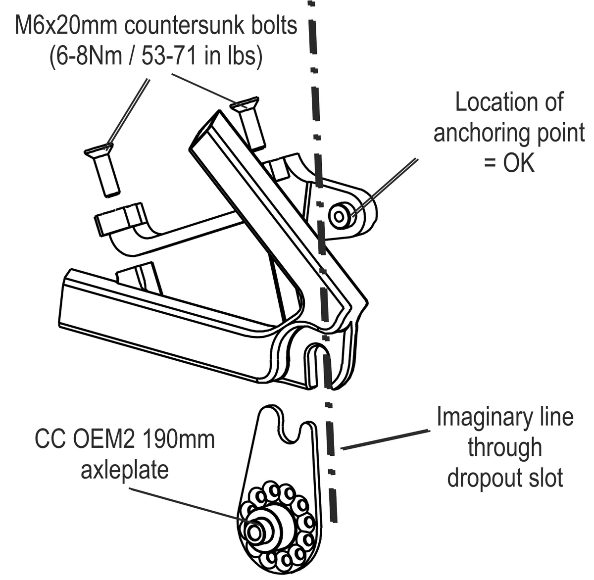
Fatbone mounting preconditions
The following pre-conditions must be adherred to in order to ensure safe mounting of the OEM2 (190/197mm) and Fatbone components:
The Rohloff OEM2 (190/197mm) axleplate must lie flush against the dropout material and may not collide with any protruding aspects of the frame (e.g. Weld beads).
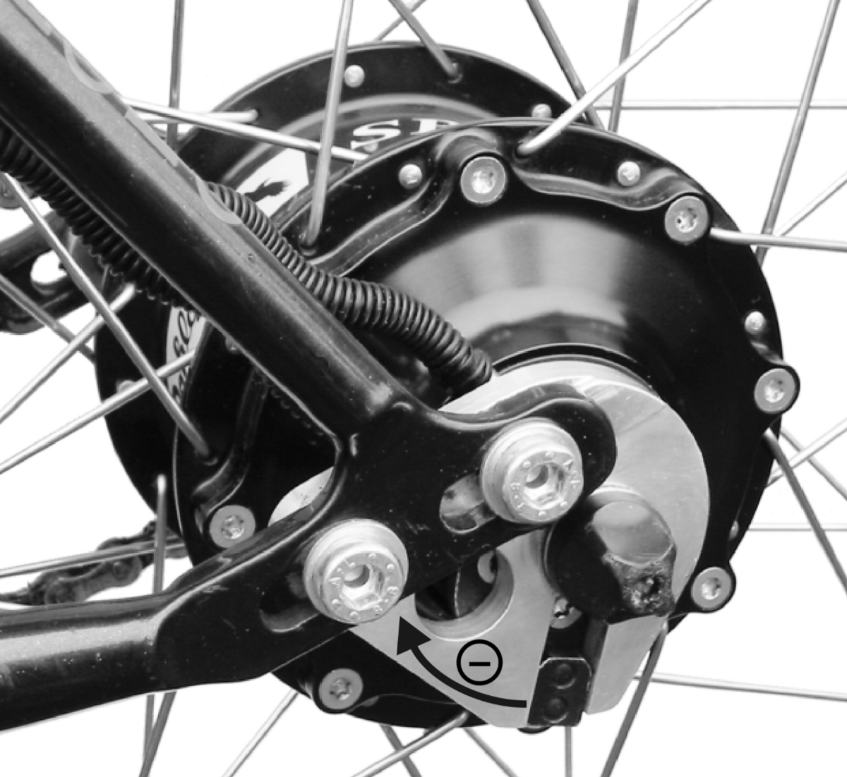
Mounting directions
- Secure the Fatbone to the direct postmount of the frame using the countersunk bolts provided.
- Mount the brake caliper to the Fatbone using the original brake mounting hardware.
- Mount the special 4-bolt brake rotor to the DB hub-cap of the SPEEDHUB.
- Simultaneously secure the axleplate to the SPEEDHUB in the corerect position.
- Check the shifter cables are routed as directly as possible (avoiding tight bends) to ensure a light shift operation.
- Mount and secure the SPEEDHUB into the frame (CC-Axle = 7Nm / 62 in lbs and A12 Axle = 15Nm / 133 in lbs).
- Finally check the braking system functions correctly and rub-free.