Process
To find out which axleplate and which torque support adapter are required by your frame, enter the disc brake mount and O.L.D. (Over-Locknut-Dimension (hub width)) in the online form. You may have to select your preferred brake rotor diameter as well. The required parts will then be displayed on the form.
Remove the appropriate demo axleplate and adapter from the measurement kit. Connect these components together and place against the frame in their usual mounted position to check for clearance and to make sure these components fit without any interference.
Should the axleplate fail to lie flush against the dropout material, or should the adapter be incompatible with the frame/dropout form, then the test is complete and we regret that we are unable to offer any SPEEDHUB model to fit this particular frame. Further testing will not be necessary.
Detailed information and a rendering showing how a correctly positioned axleplate should look, can be found below.
For 142mm, 148mm and 177mm frame spacings
Axleplate Options
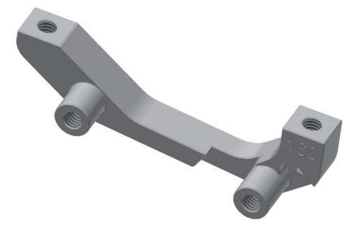
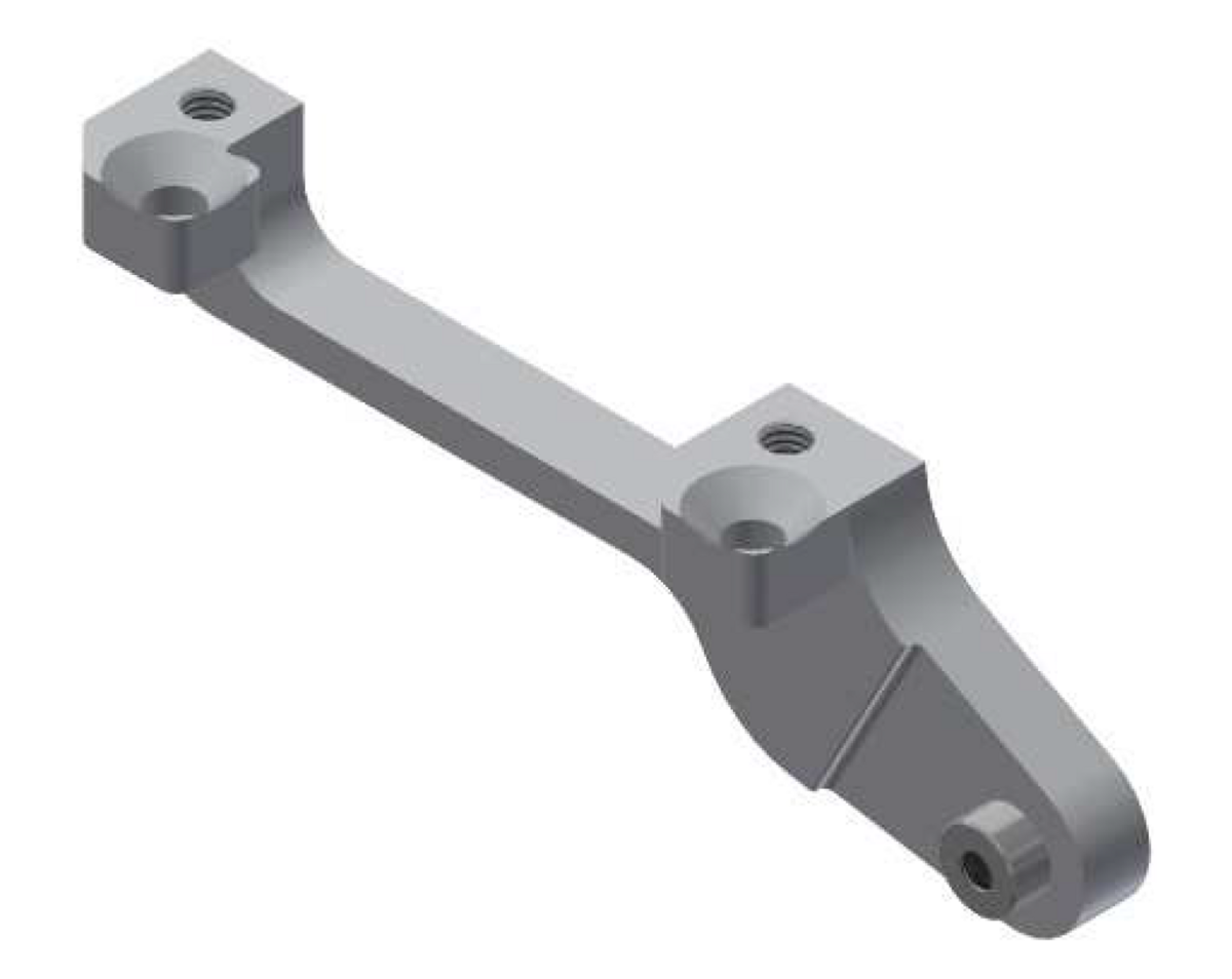
Torque Anchoring Adapter Options
For 197mm frame spacing
Required Axleplate
Torque Anchoring Adapter Options
Frames with a Postmount disc brake mount using a Postmount brake caliper
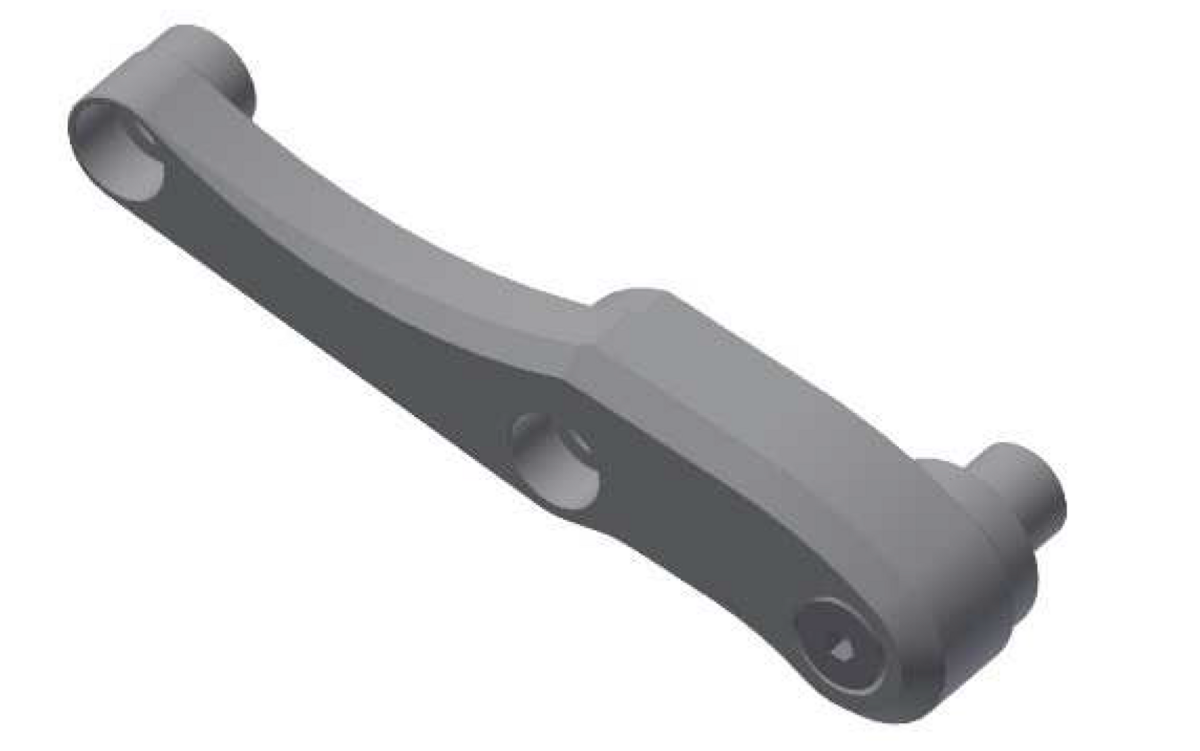
Frame designed for 160mm brake discs =
FAT Bone 180 Art. No. 8556
Pointer: The FAT Bone 180 functions as an adapter from a 160 to 180mm rotor. A 180mm brake rotor will therefore always be required when fitted to a frame which is actually designed for a 160mm caliper.
Frames with a Postmount disc brake mount using a Postmount brake caliper
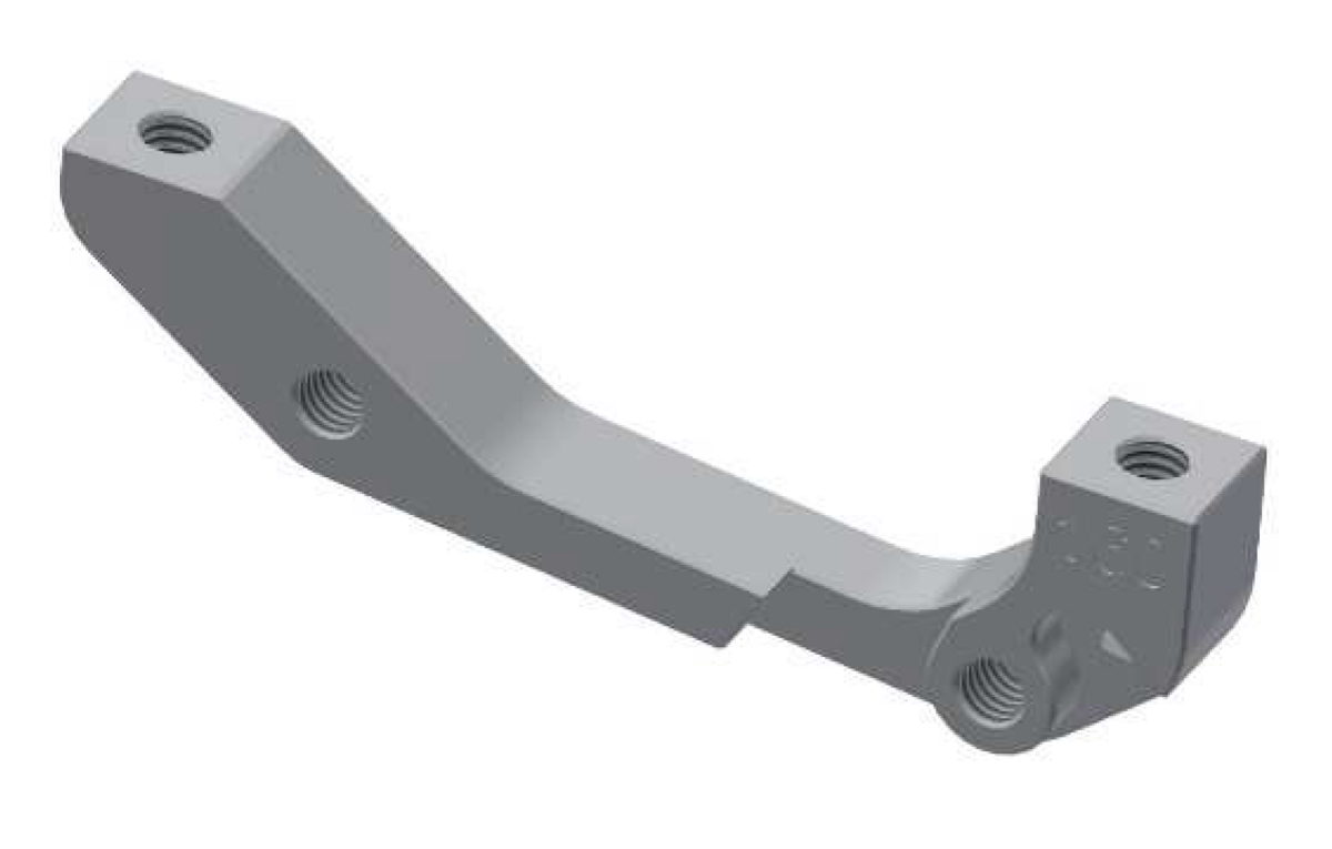
Frame designed for 180mm brake discs =
FAT Bone 203 Art. No. 8557
Pointer: The FAT Bone 203 functions as an adapter from a 180 to 203mm rotor. A 203mm brake rotor will therefore always be required when fitted to a frame which is actually designed for 180mm caliper.
Flush Mounting of the Axleplate
It is vital to ensure the axleplate lies completely flush against the inside dropout face. Make sure weld beads and stay material is not located underneath the axleplate. Failure to do so will result in the SPEEDHUB sitting incorrectly in the dropout and thus hindering the brake rotor running parallel through the brake calliper.
How to check the correct position of the axleplate:
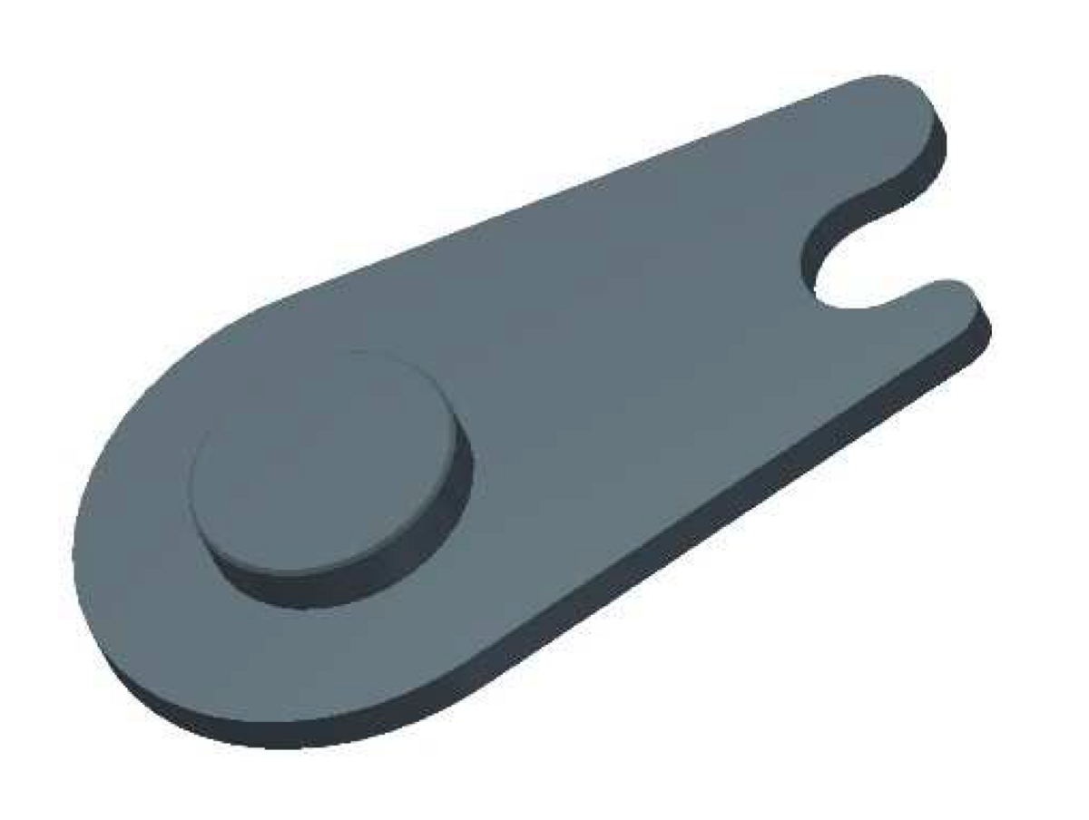
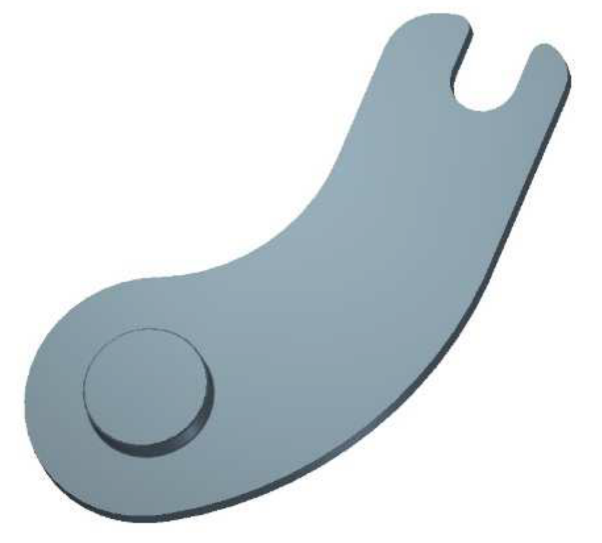
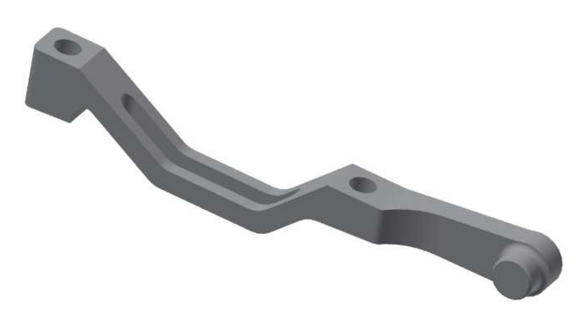
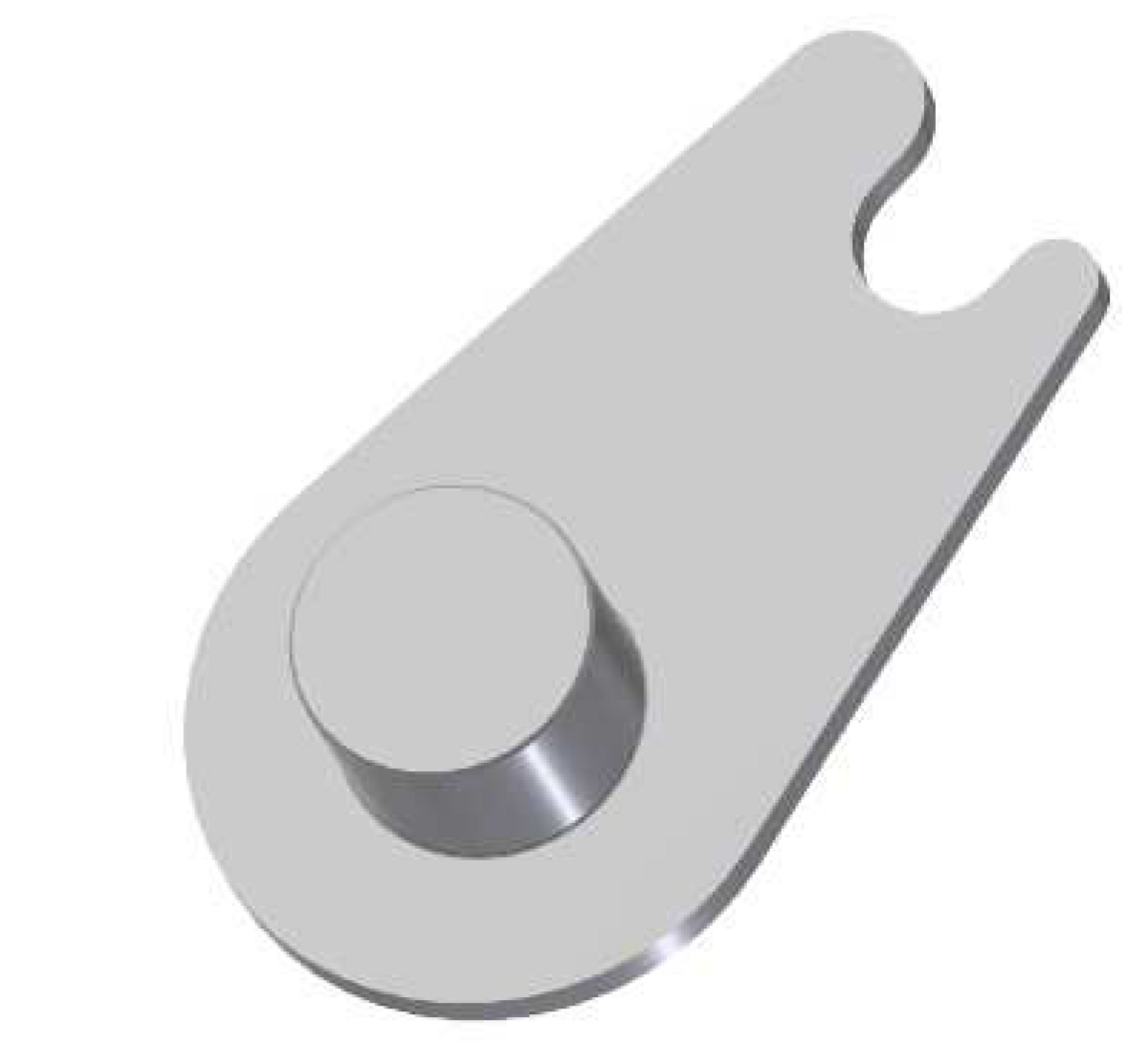
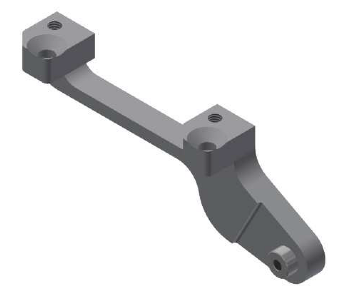
All SPEEDHUB models anchor the output torque of the hub to the left-hand (disc brake) side of the frame through the use of an adjustable and interchangeable axleplate.
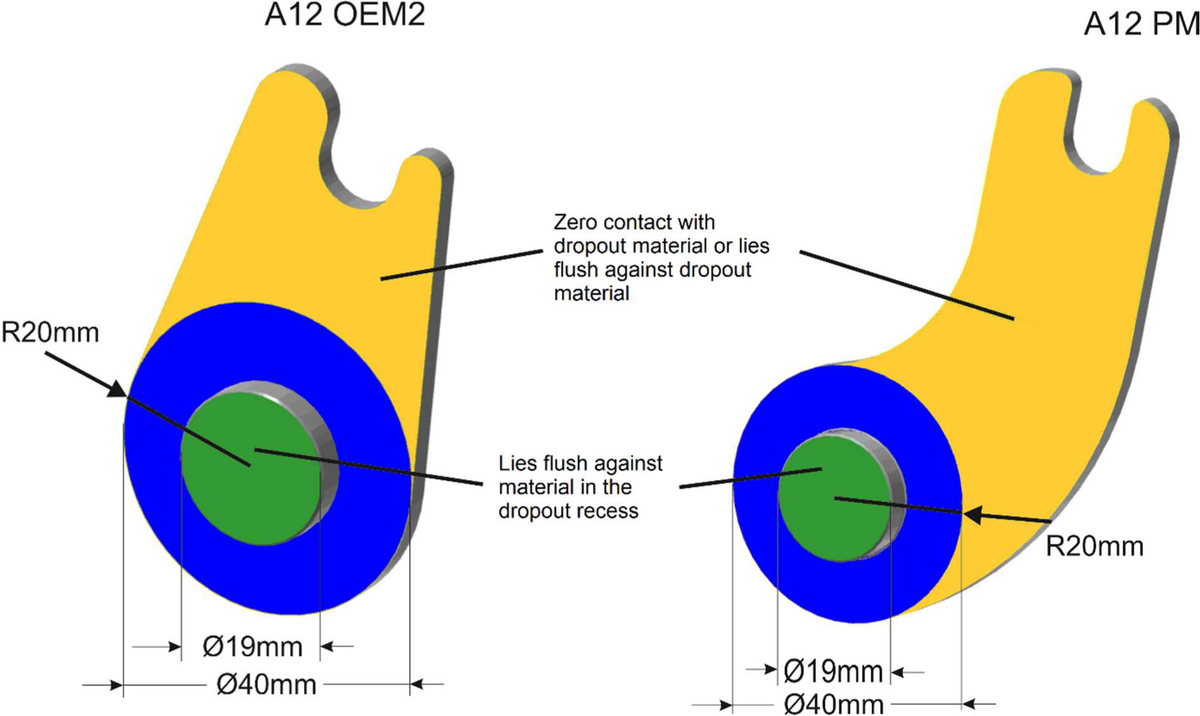
Contrary to regular hub axles, which make contact with the dropout with just a 19mm diameter lock-nut, the axle contact area on this side of a SPEEDHUB (the axleplate) measures 40mm diameter (blue). In addition, each axleplate is designed with a 19mm diameter axle stud (green) for ease locating the hub in the dropout and will require enough dropout/frame clearance to accommodate the area transferring the output torque to the adapter/frame (yellow).
The yellow section of the selected axleplate must lay completely parallel to the dropout material whereby it doesn’t matter if this yellow area actually touches the dropout material or not.
The yellow section of the axleplate will lie in a different position against the dropout surface, depending upon the desired direction of cable routing selected.