Shifter cables
Cable Manager Kit
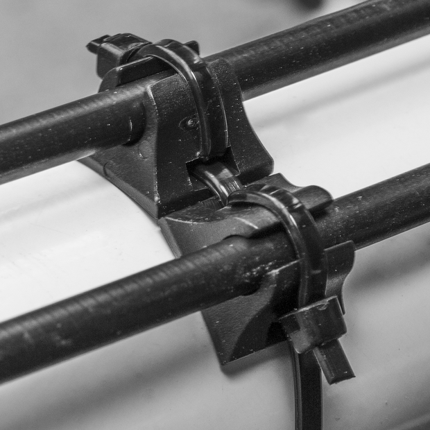
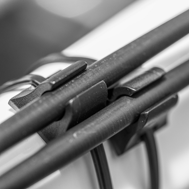
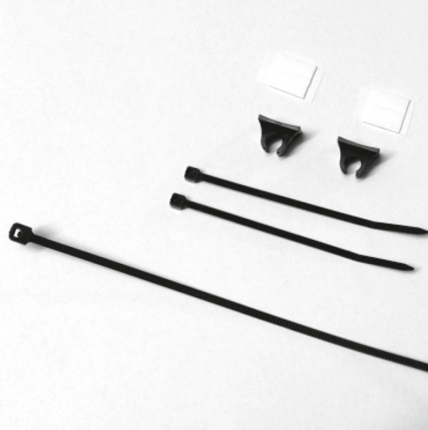
A special Cable Manager Kit (Art. #5201) is available consisting of 3 cable ties, 2 double sided sticky tabs and 2 guides that secure the SPEEDHUB shifter cables to the frame. One kit will hold a cable secure in two positions - a great way to secure cables to frames without brazed-on guides.
For a cable casing change, the cable tie on the frame does not need to be replaced. The two smaller cable ties need to be renewed.


Internal gear mech
Cable routing via the brake boss
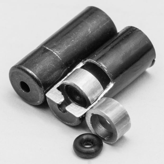
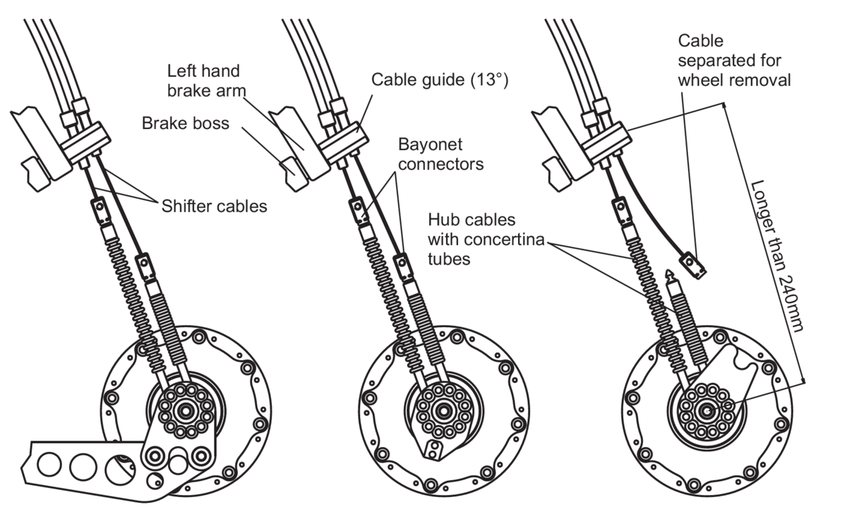
With the internal gear mech the shifter cables run from the twist shifter to the cable guide, which can be mounted to the left hand brake boss or clamped to the left hand chainstay. The internal gear mech involves the use of two hub cables. They must be connected to the shifter cables by the use of bayonet connectors which allow a quick separation for wheel removal.
The internal gear mech is not compatible with the use of a rear disc brake as the hub cables and bayonet connectors may rub on the disc.
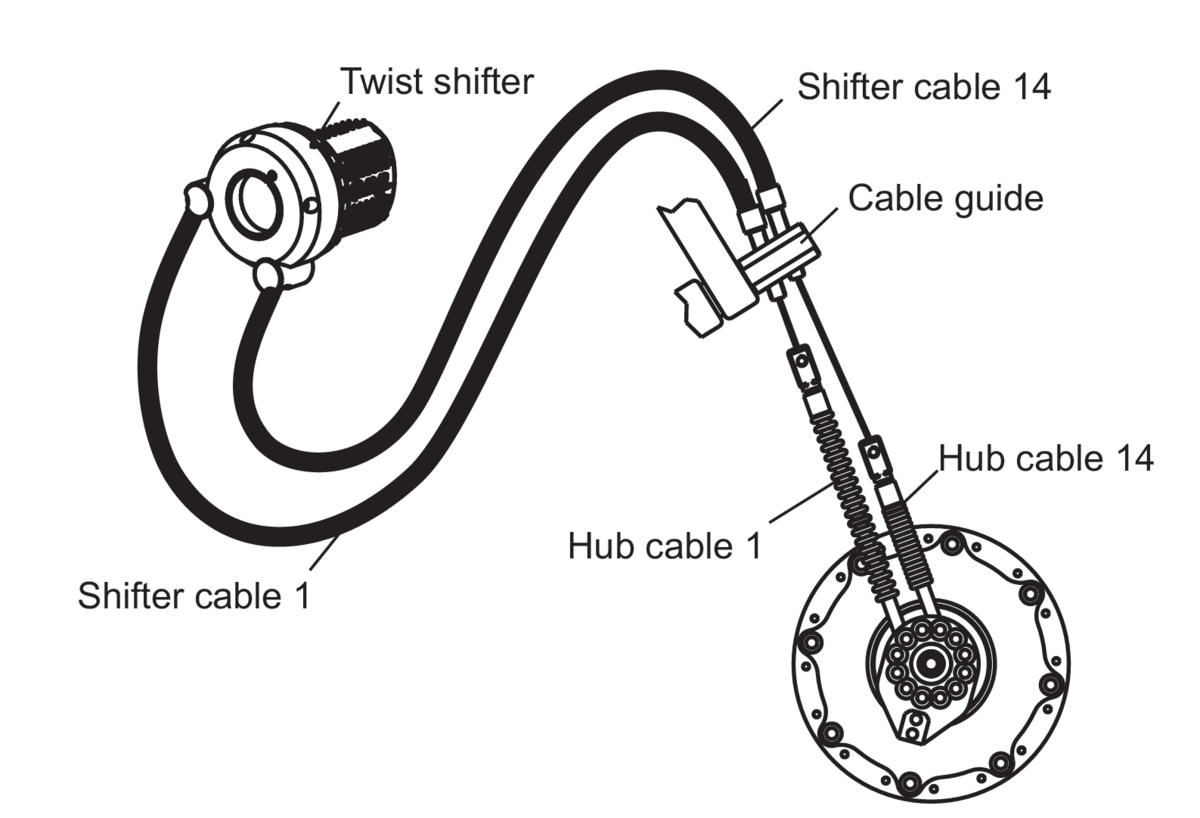
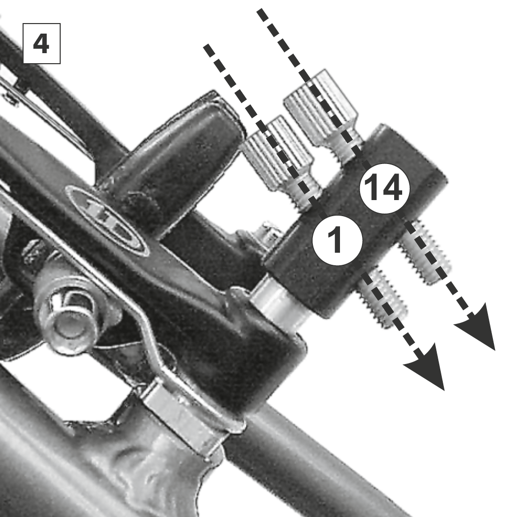
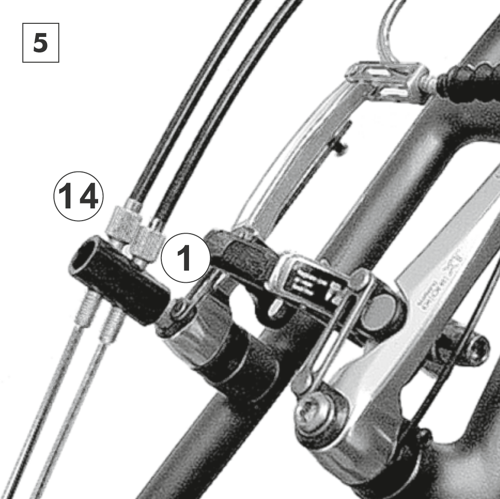
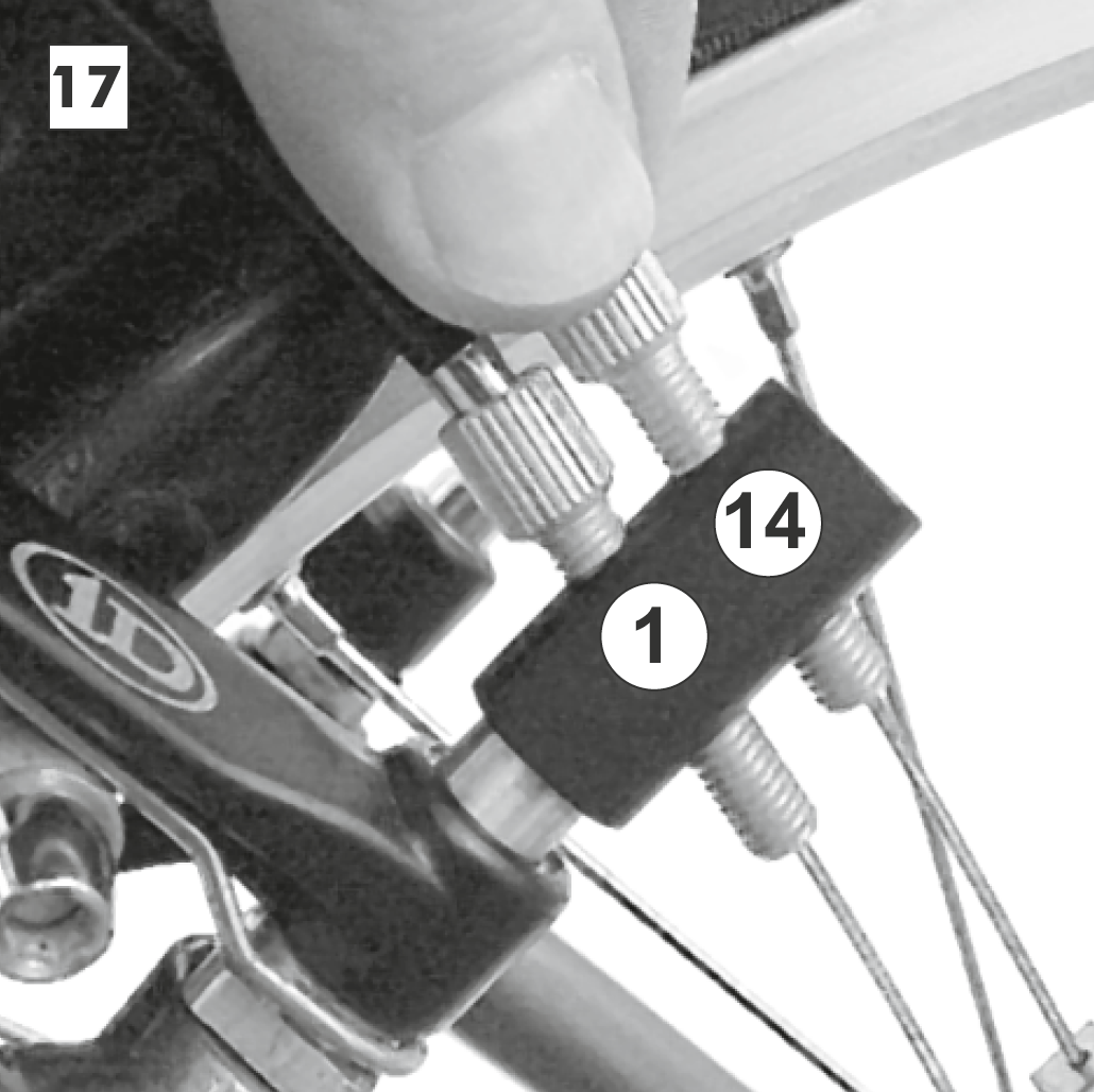
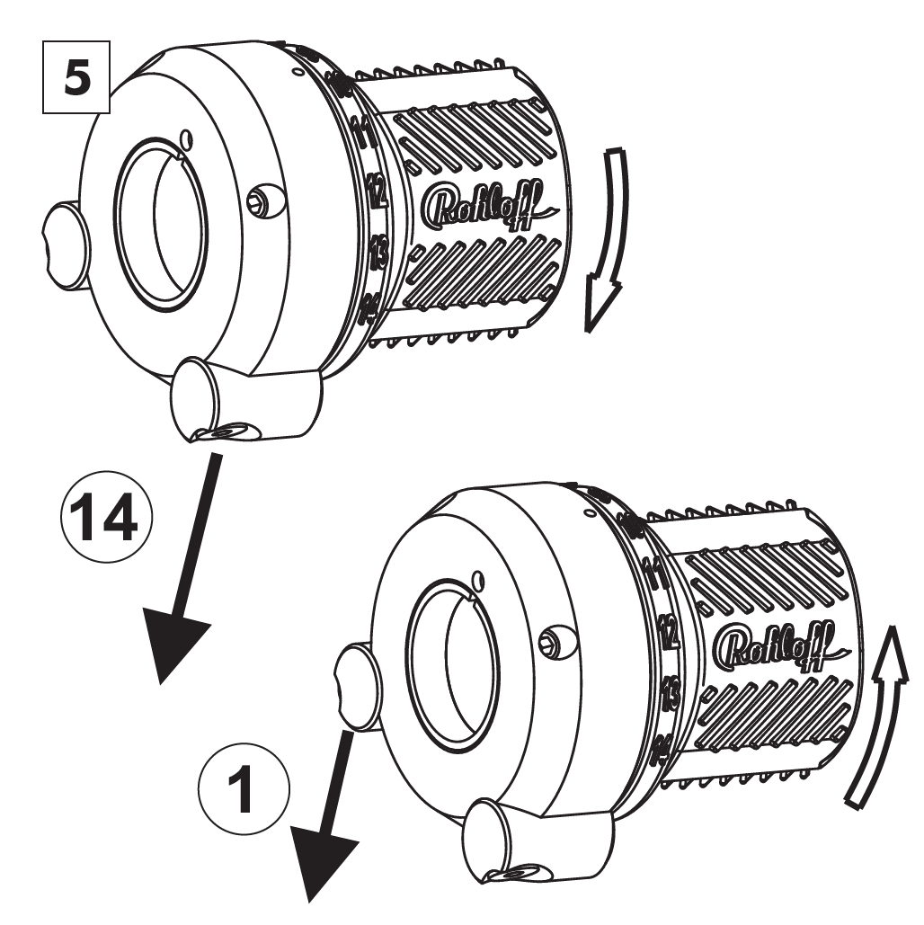
When pulling the shifter cable 1, lower gears are engaged. When pulling the shifter cable 14, higher gears are engaged. Gear cable 1 lies to the front of the twist shifter as well as to the front of the cable guide. Gear cable 14 lies to the back of the twist shifter as well as to the back of the cable guide.

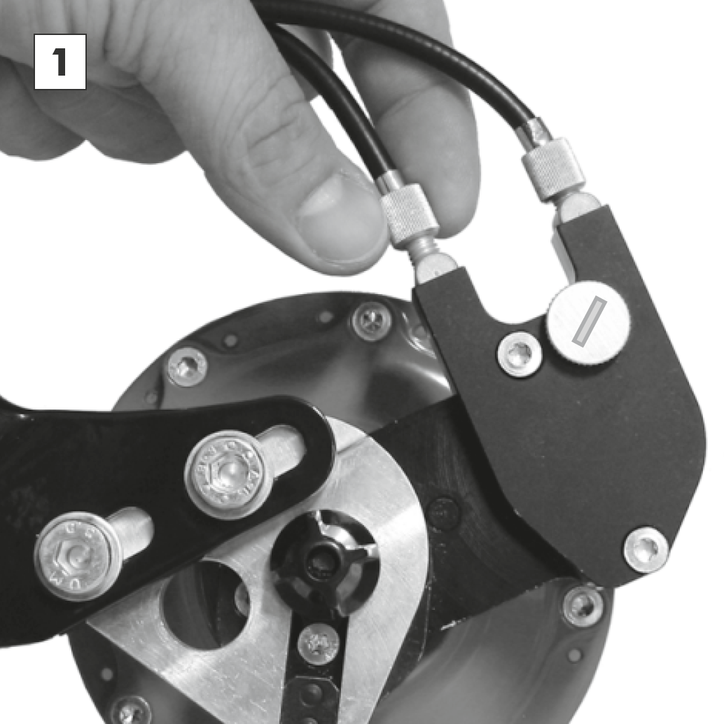
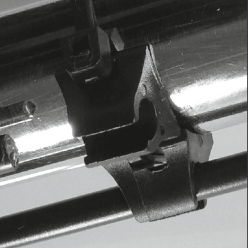
When routing the shifter cables of the internal gear mech along the top tube, the cable guide is mounted to the brake boss. Prior to routing the cables, the cable guide must be secured to the left side brake boss. The original brake boss securing bolt must be removed (this will be replaced with the new bolt supplied). All other parts of the brake remain in place.
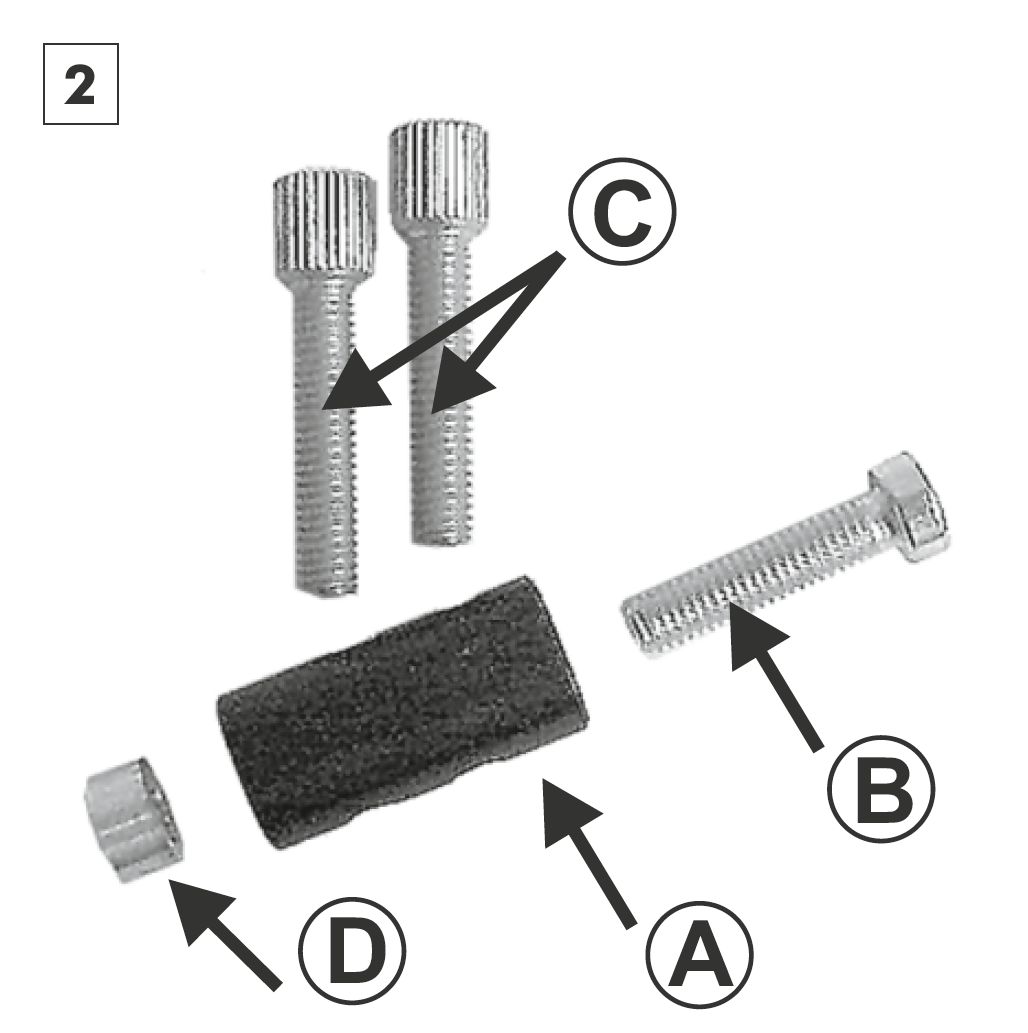
Cable guide 13°:
A Cable guide
B Mounting bolt (M6x25)
C Cable adjuster (2x)
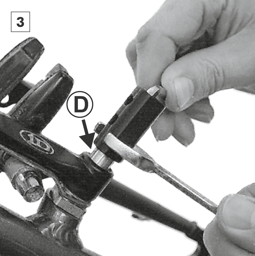
D Spacer
Spacer D must be used when:
- Mounting bolt is too long for securing to the brake boss
- Cable guide A interferes with the smooth running of the brake operation (eg parallel push linkage certain types of V-brake system).

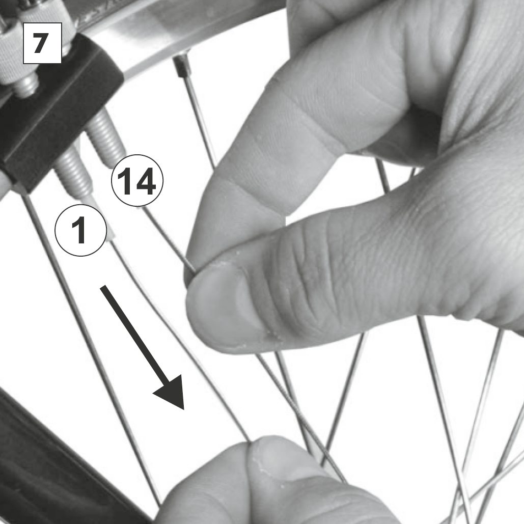
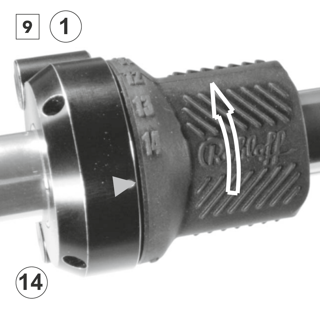
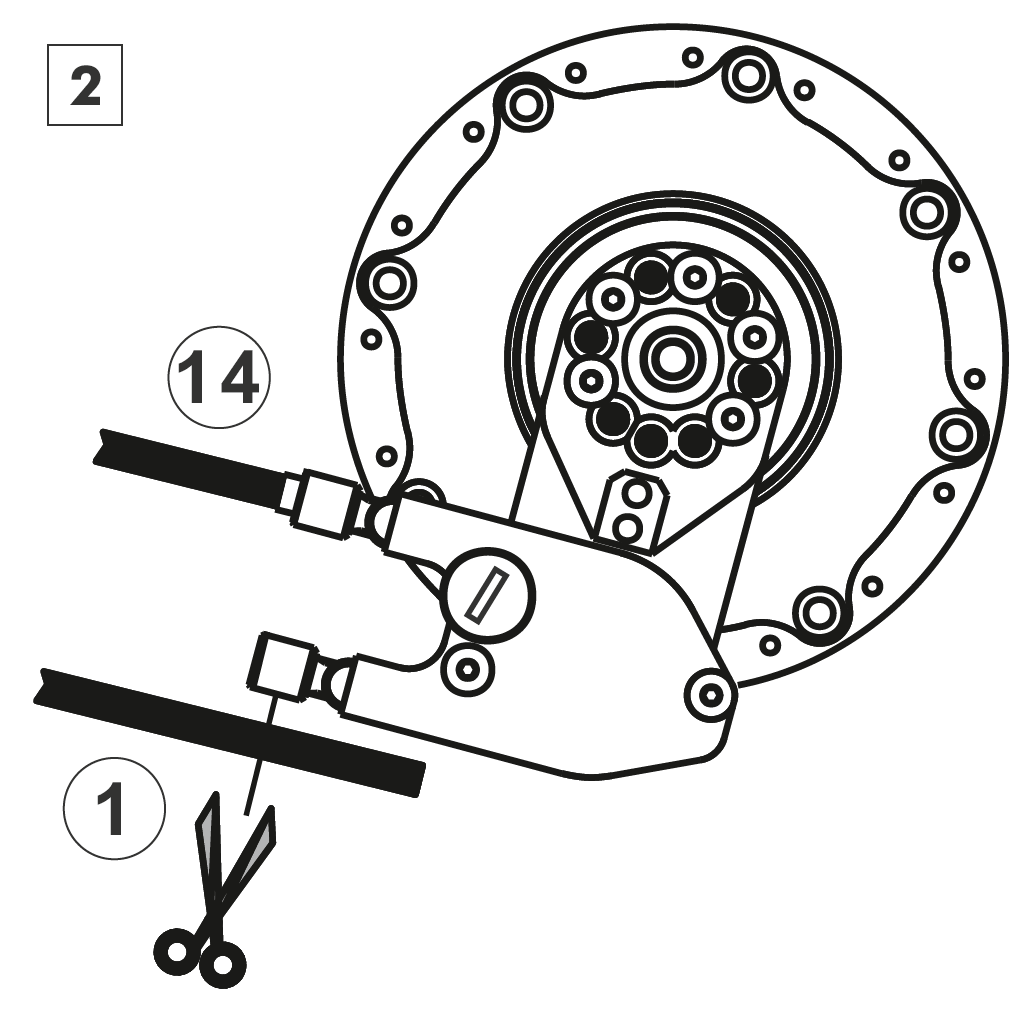
Pull both shifter cables to the end stop in turn to make sure that the cable housings sit correctly in the cable stops. When pulling shifter cable 14, the twist shifter should turn in the direction of gear indicator #1. When pulling shifter cable 1 the twist shifter should turn in the direction of gear indicator #14. Should this not be the case, switch over the cables within the cable guide.


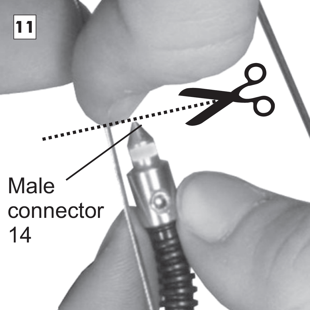


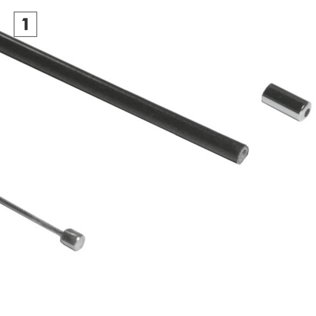
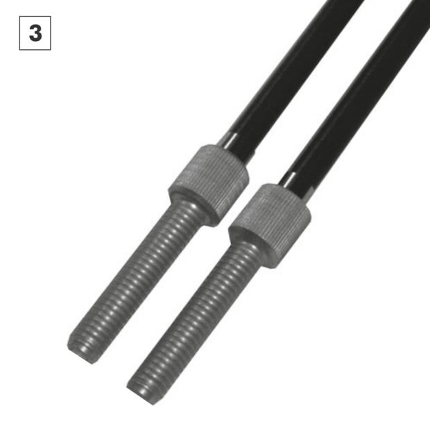
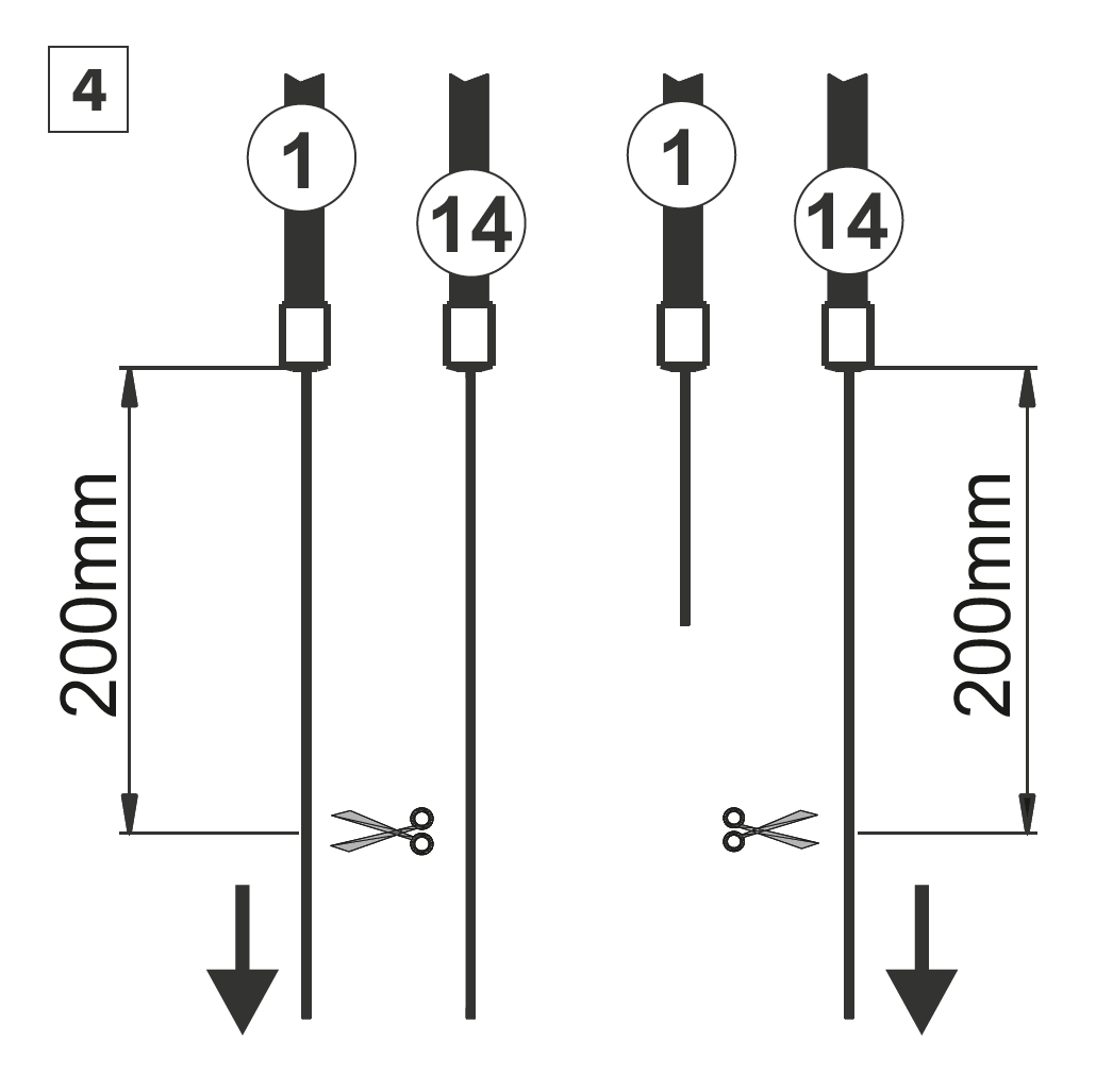
Pull hub cable 1 out by the bayonet connector until its end stop. The connected shifter cable 14 will automatically be pulled in the other direction. Pull shifter cable 1 tight, so that the cable is tensioned and hold it up against hub cable 1. Cut the shifter cable at the point level with the top of the bayonet connector.
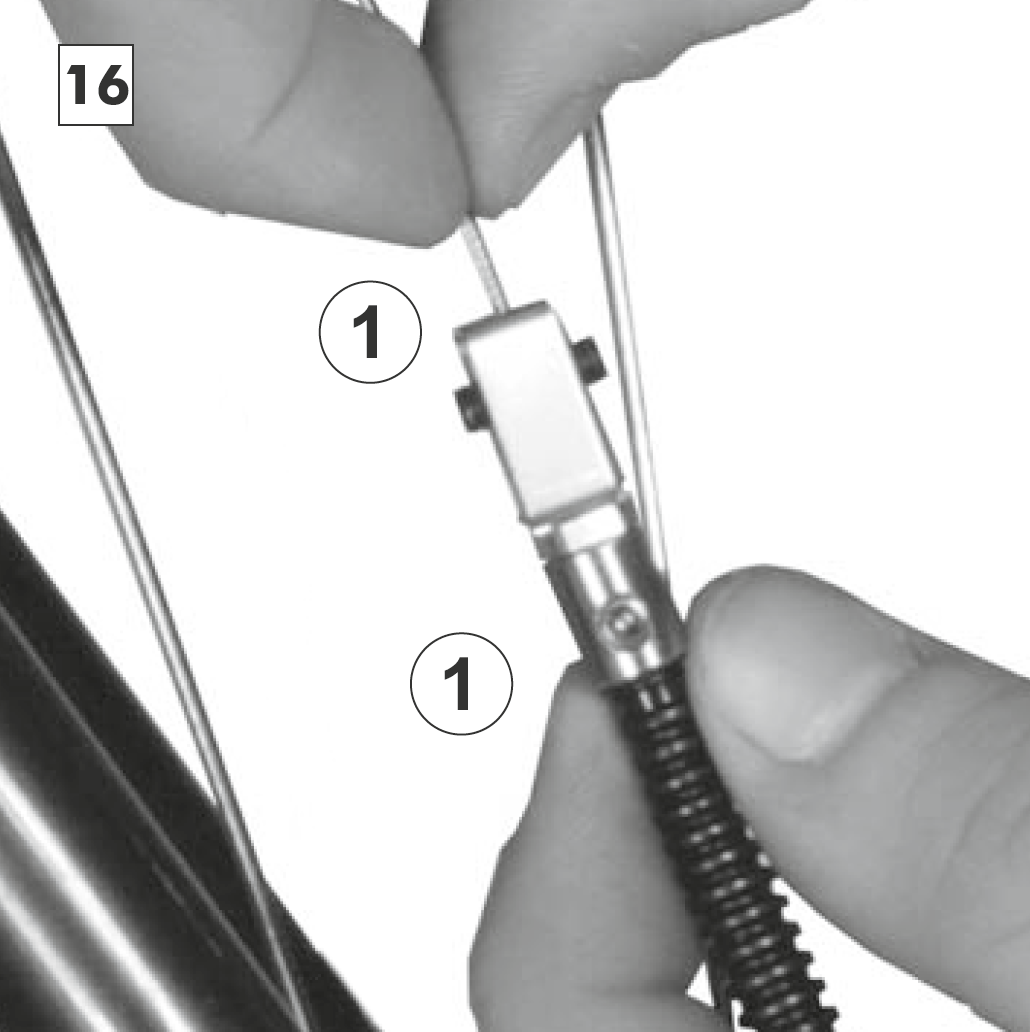
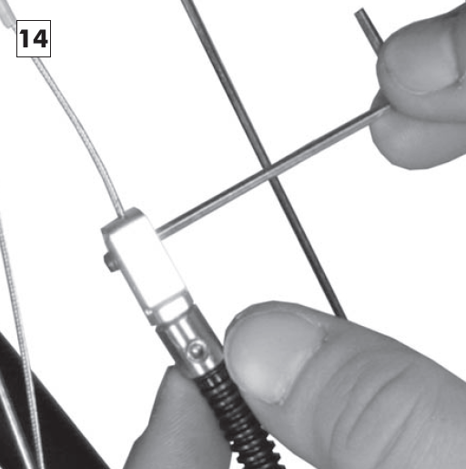
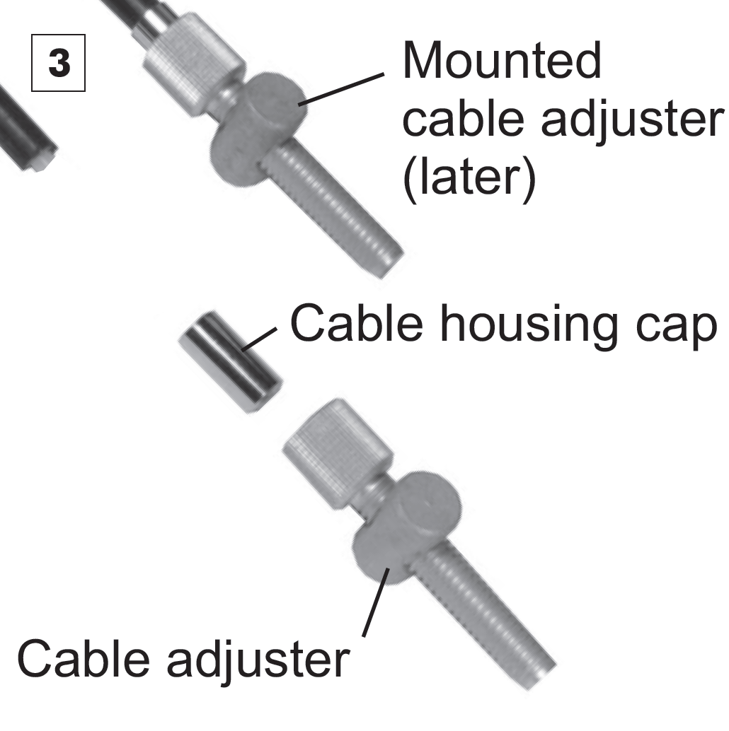
Open the male/female connectors of cables 14, so that joining shifter cable 1 with a female connector becomes easier. Place the female connector over the male bayonet connector and thread the shortened shifter cable 1 fully into the hole of the bayonet connector 1 (10mm deep), tighten up the headless screws. Rejoin the disconnected cables 14.
Turn the twist shifter back and forth several times to make sure that the shifter cables are sitting correctly within the cable guides. For a lighter shifting, set the cable tension (by the use of the cable adjusters), so that the twist shifter has about 2mm play. Winding out the cable adjusters increases the shifter tension, winding the cable adjusters in decreases the shifter Tension.

Cable routing via the chainstay
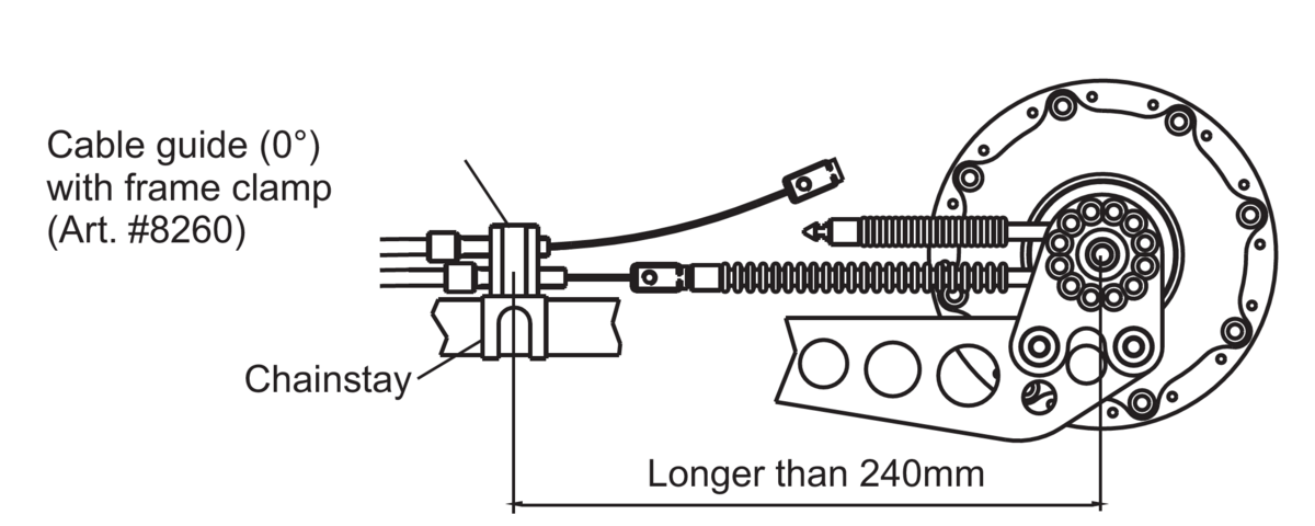
When routing the shifter cables via the chainstay, the 0° cable guide (Art. #8260) must be mounted at a minimum distance of 240mm away from the hub's axle. This should be mounted in a position, so that the hub cables run in the straightest line possible towards the shifter cables.
The diagram shows an example of the internal gear mech routed via the chainstay with the standard axle plate and long torque arm using the 0° cable guide and frame clamp.
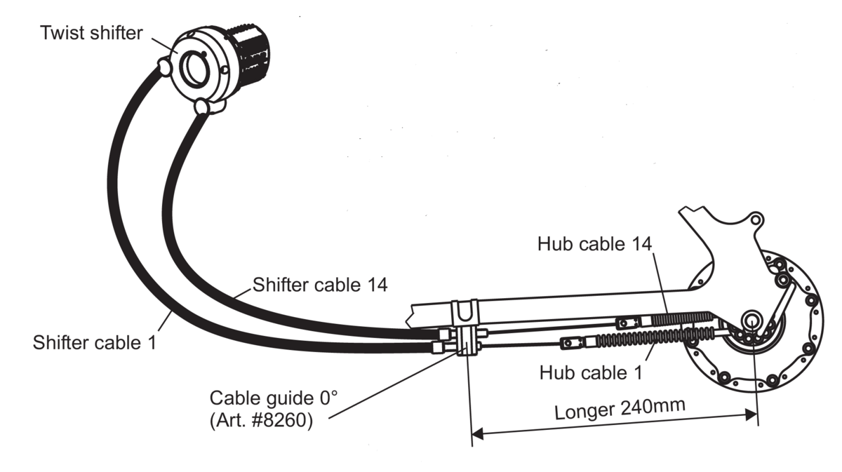
By pulling hub cable 1, the gearbox shifts gears in direction of gear #1 (smaller gears). By pulling hub cable 14, the gearbox shifts gears in direction of gear #14 (larger gears). Hub cable 1 lies in the lower position at the gearbox and at the front position on the twist shifter. Hub cable 14 lies in the higher position at the gearbox and at the rear position on the twist shifter. The connecting of the shifter cables to the hub cables is explained in chapter 7.2.1
External gear mech
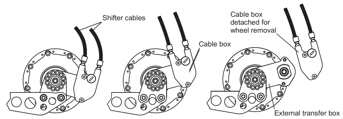
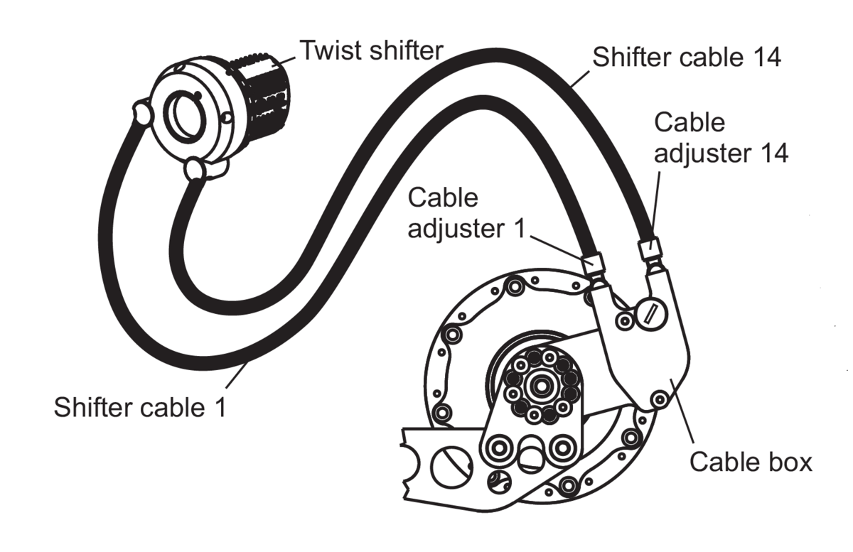
With the external gear mech the shifter cables run directly from the twist shifter to the cable box. There is no separate cable stop necessary. For quick and easy removal of the rear wheel, the cable box can be removed from the external transfer box. All disc brake versions (DB) of the Rohloff SPEEDHUB 500/14 are equipped with the external gear mech. The hole pattern in the axle plate allows the adjustment of the gear mech in steps of 30°. Therefore, an optimum cable routing can be achieved for nearly all frame types.
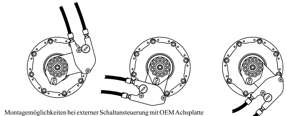
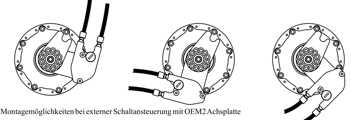
Mounting options
External Gear Mech - cable replacement
Cable routing via the chainstay
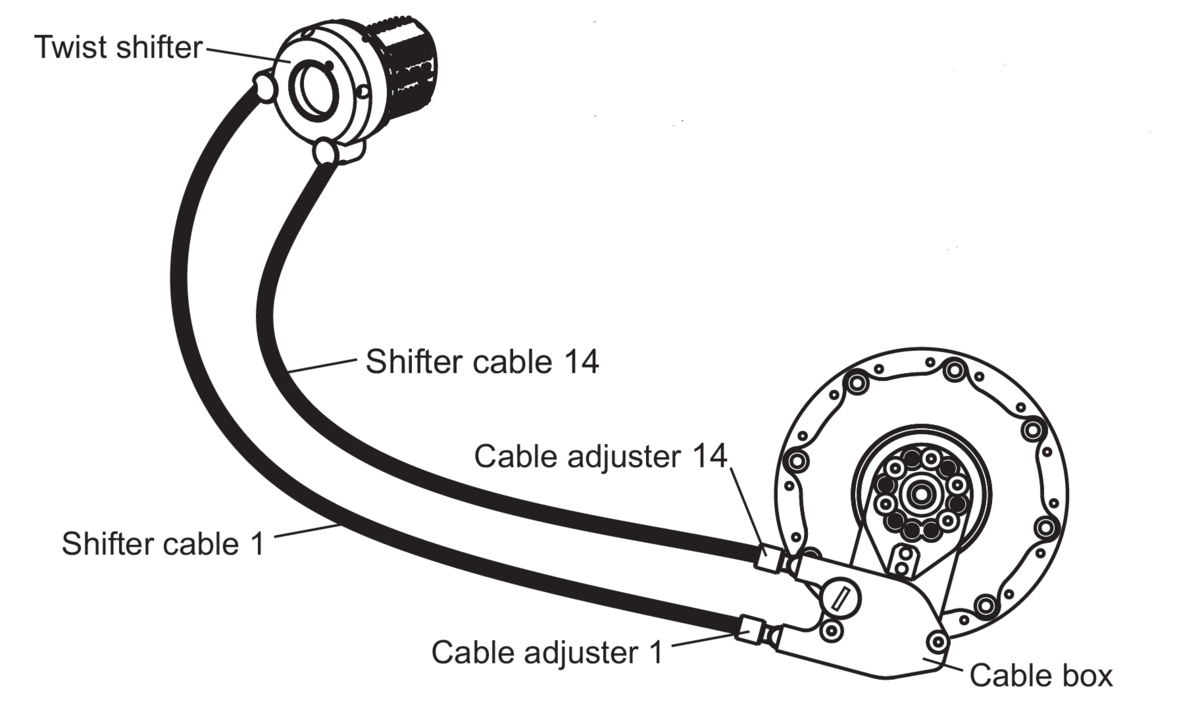
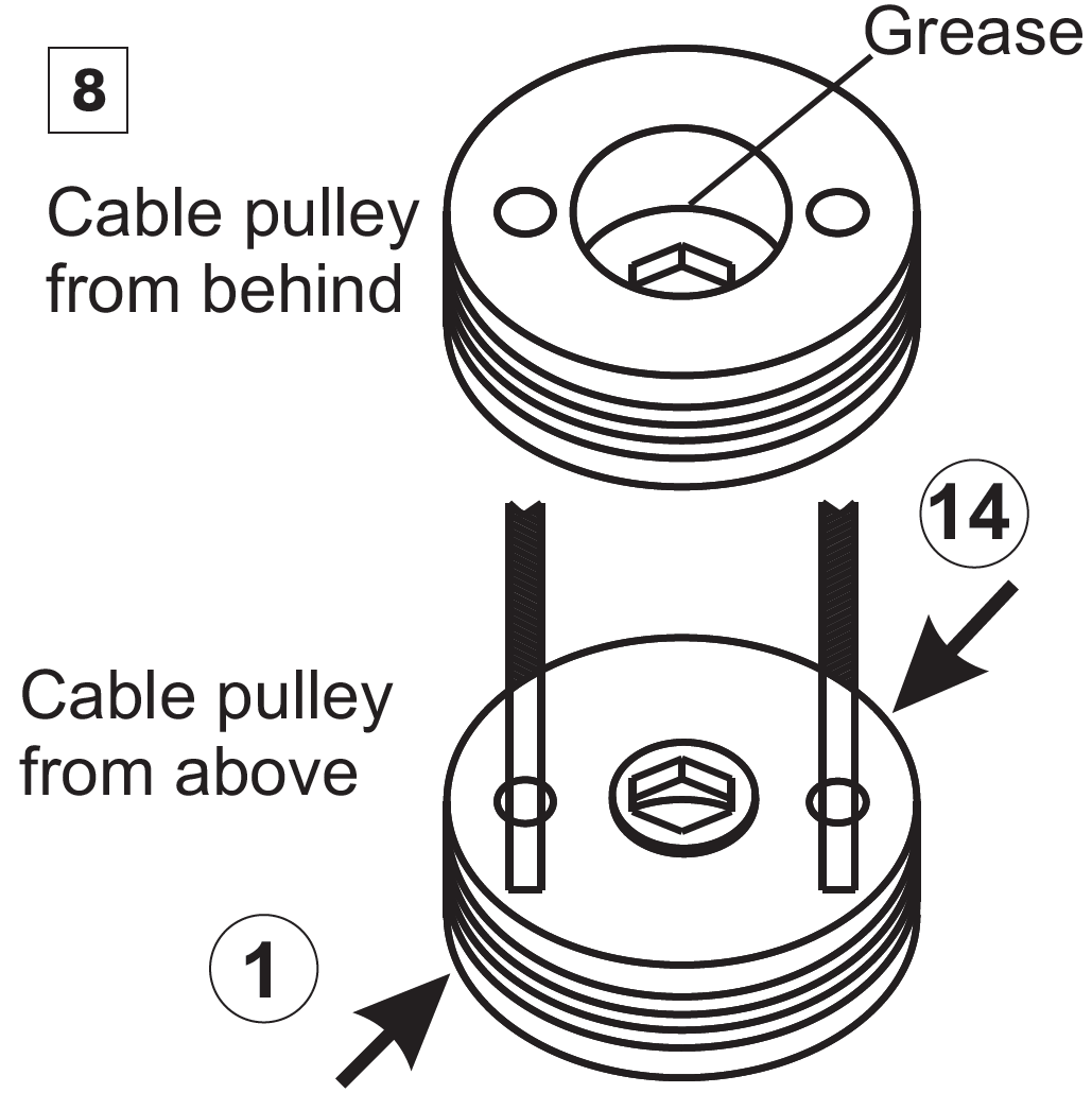
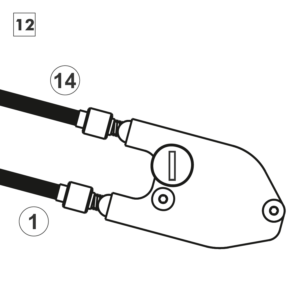
By pulling hub cable 1, the gearbox shifts gears in direction of gear #1 (smaller gears). By pulling hub cable 14, the gearbox shifts gears in direction of gear #14 (larger gears). Hub cable 1 lies in the lower position at the cable box and at the front position on the twist shifter. Hub cable 14 lies in the higher position at the cable box and at the rear position on the twist shifter.
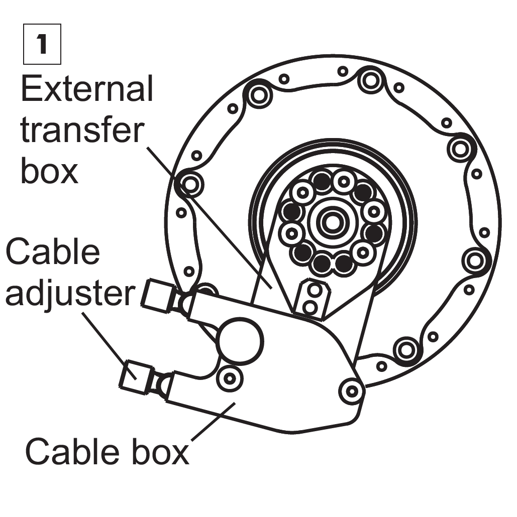
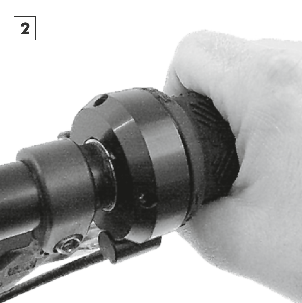
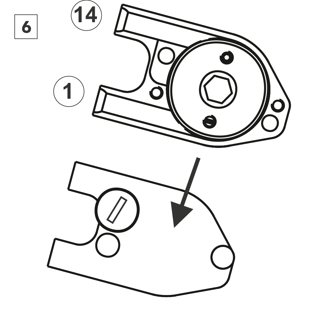
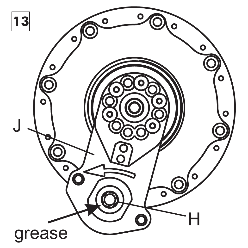
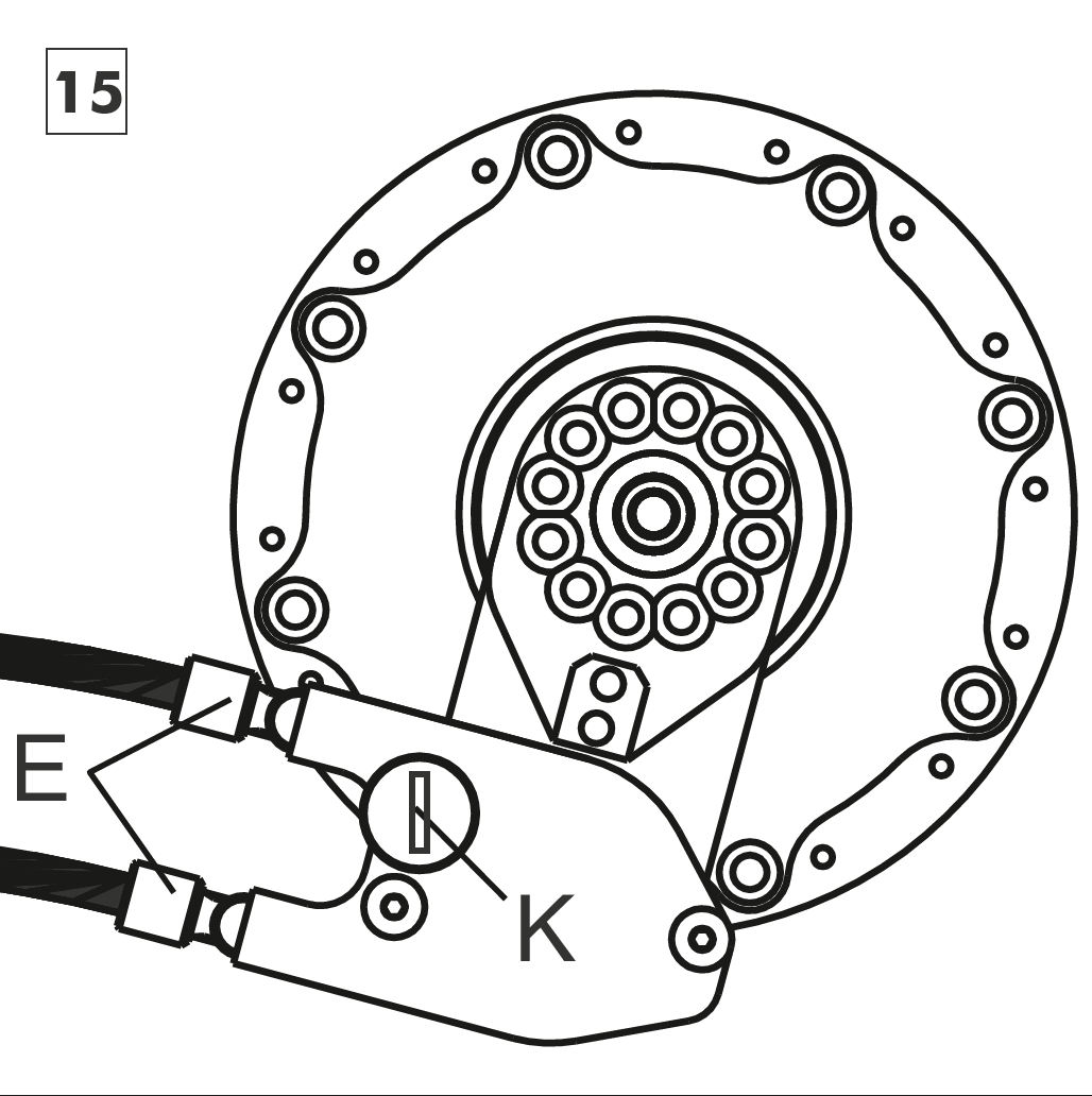
Secure the cable box to the external transfer box (which should be in the correct, preadjusted position) with the knurled headed screw. Insert the two cable adjusters into the cable box. The diagram shows the gear transfer box mounted in line with an OEM axle plate but the type and position of axle plate can vary from that illustrated.
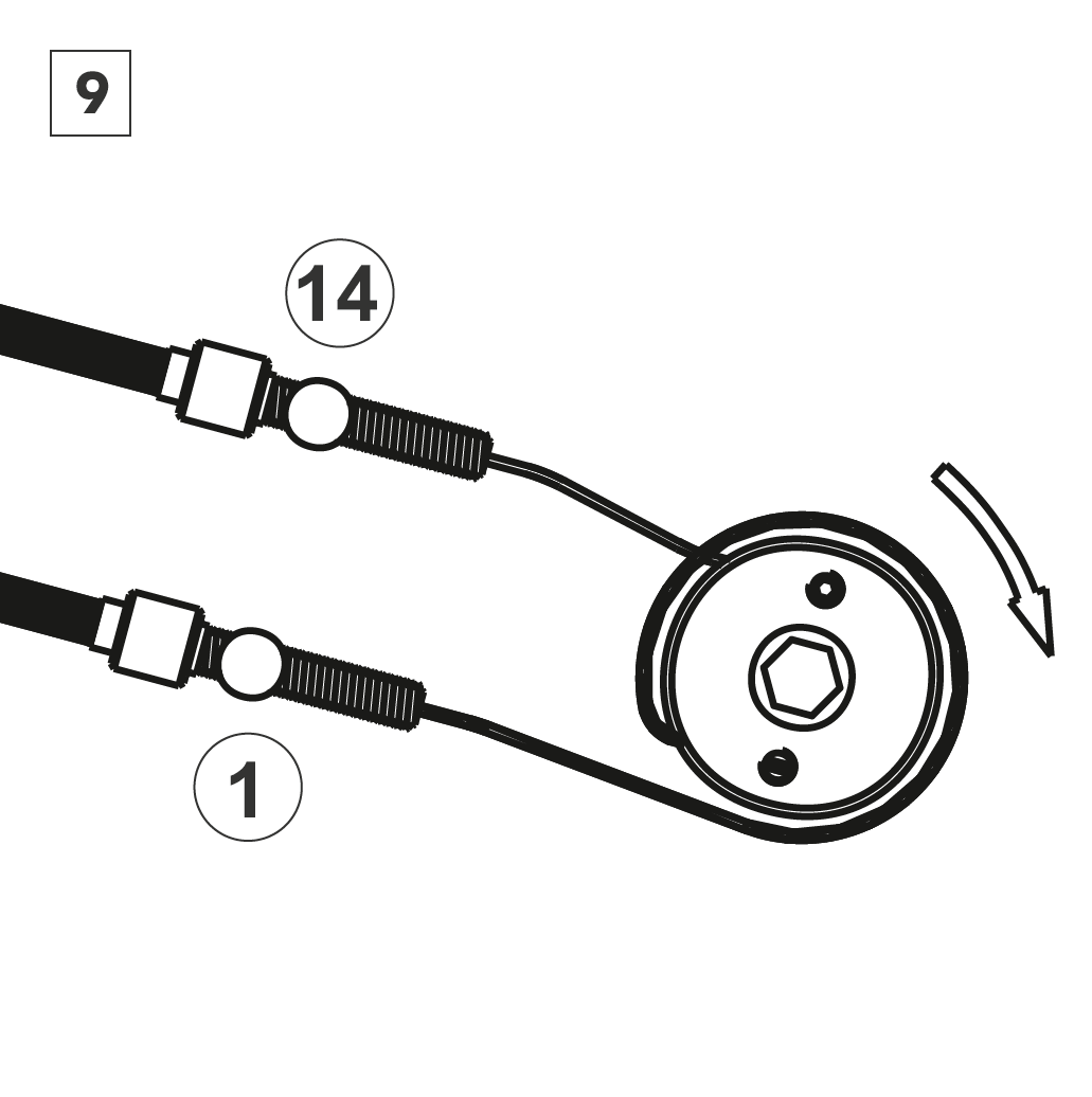
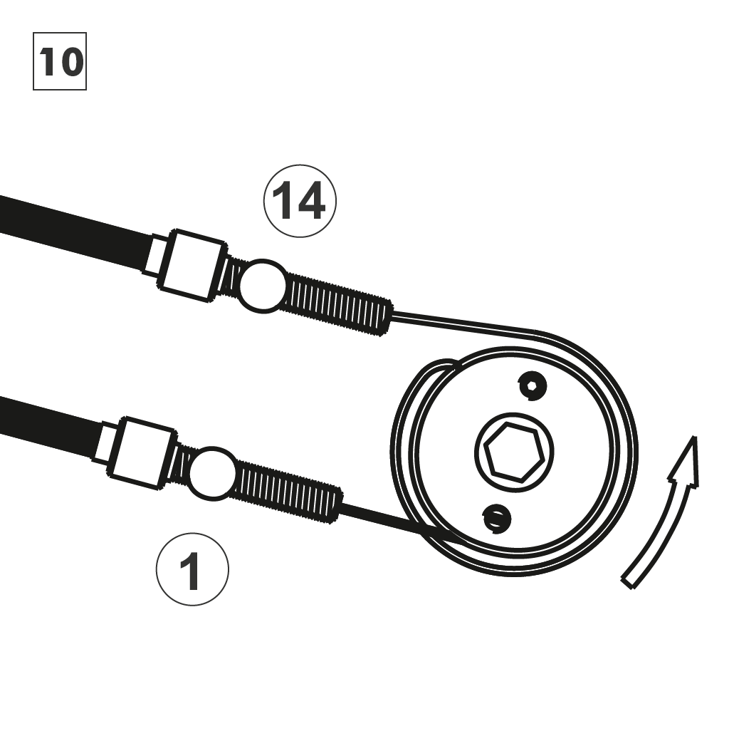
Insert the shifter cables into the cable adjusters. Pull out shifter cable 14 as far as possible, the twist shifter will rotate in the direction of end stop 1. Pull out shifter cable 1 as far as possible, the twist shifter will rotate in the direction of end stop 14. To make sure that the gear display doesn't get reversed, check that the lower shifter cable on the twist shifter is fed into the top adjuster on the cable box.


Cable routing via the top tube
By pulling hub cable 1, the gearbox shifts gears in direction of gear #1 (smaller gears). By pulling hub cable 14, the gearbox shifts gears in direction of gear #14 (larger gears). Hub cable 1 lies in the front position at the cable box and on the twist shifter. Hub cable 14 lies in the rear position at the cable box and on the twist shifter.