Have Test Components Ready

First Measurement Process: Reduction Sleeves
Disc Brake Side (left-hand)

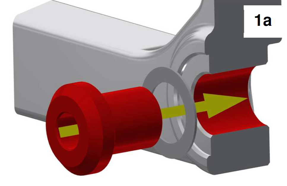
1. Min. Play Test 0.5 mm (Dropout Thickness)
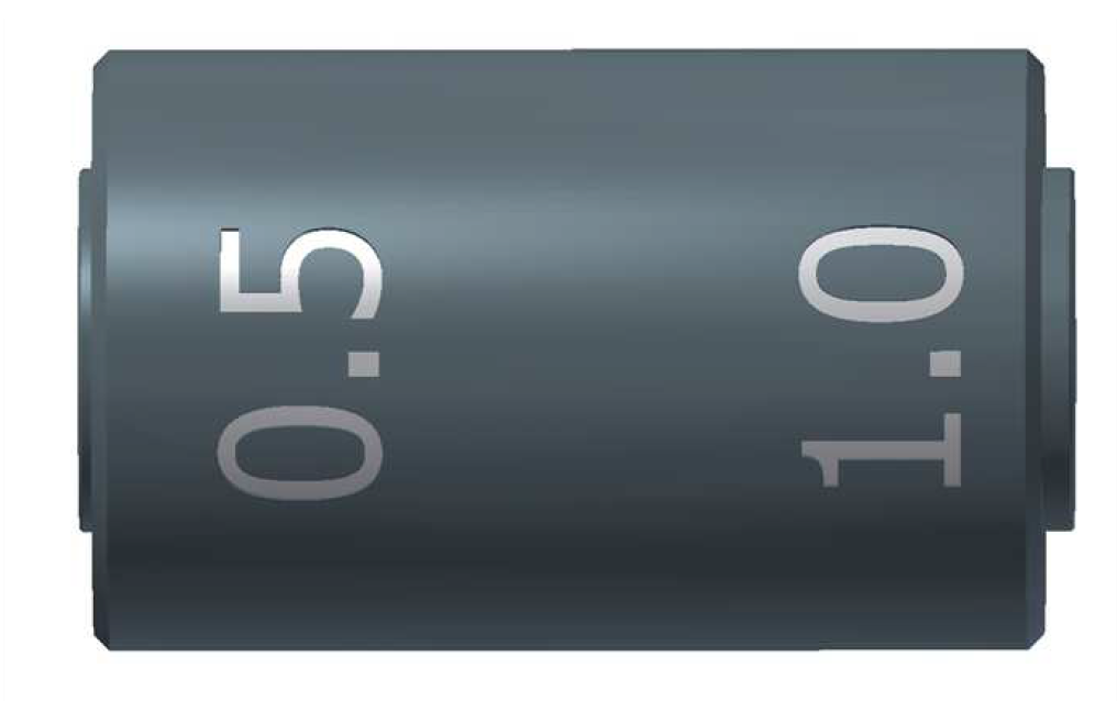
Use the 0.5 mm side of the A12 Dropout Gauge on the back of the left-hand dropout. Use a two-finger wiggle to check whether there is lateral play or not.
Lateral play: Dropout too thin. Go to 1a) Fit Micro Shim.
Zero lateral play: 0.5 mm test result left-hand dropout OK. Proceed to 2) Max. Play Test 1.0 mm.
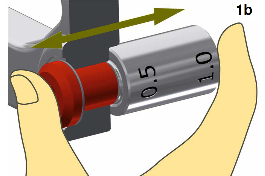
1b. Check Fit
Check whether there is still lateral play or not.
Lateral play: Fit another micro shim and check again.
Zero lateral play: 0.5 mm test result OK. Testing of the left-hand dropout is complete. Max. play test 1.0 not necessary. Note number of required micro shims in the order form. Proceed to 3) Sprocket Side (right-hand).
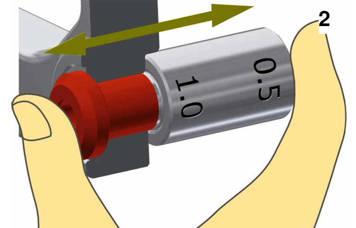
2. Max. Play Test 1.0 mm (Dropout Thickness)
Use the 1.0 mm side of the A12 Dropout gauge on the back of the left-hand dropout. Check whether there is lateral play or not.
Zero lateral play: Dropout too thick. Go to 2a) Fit Sleeve with Micro Shims.
Lateral play: Test result OK. Testing of the left-hand dropout is complete. Proceed to 3) Sprocket Side (right-hand).

2a. Fit Sleeve with Micro Shims
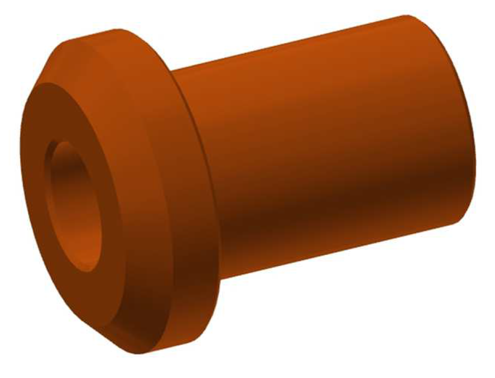
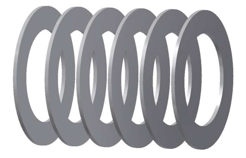
Fit extended A12 reduction sleeve (orange) with all six 0.5mm micro shims.
Go to 2b) Check Fit.
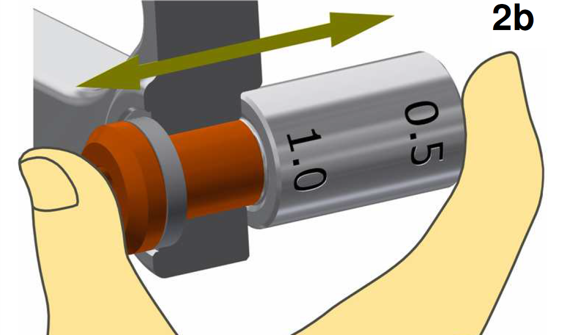
2b. Check Fit
Check whether there is lateral play now or not.
Zero lateral play: Remove one micro shim and repeat the process.
Lateral play: Test result OK. Custom reduction sleeve required. Note number of remaining micro shims on the order form. Proceed to 3) Sprocket Side (right-hand).
Sprocket Side (right-hand)
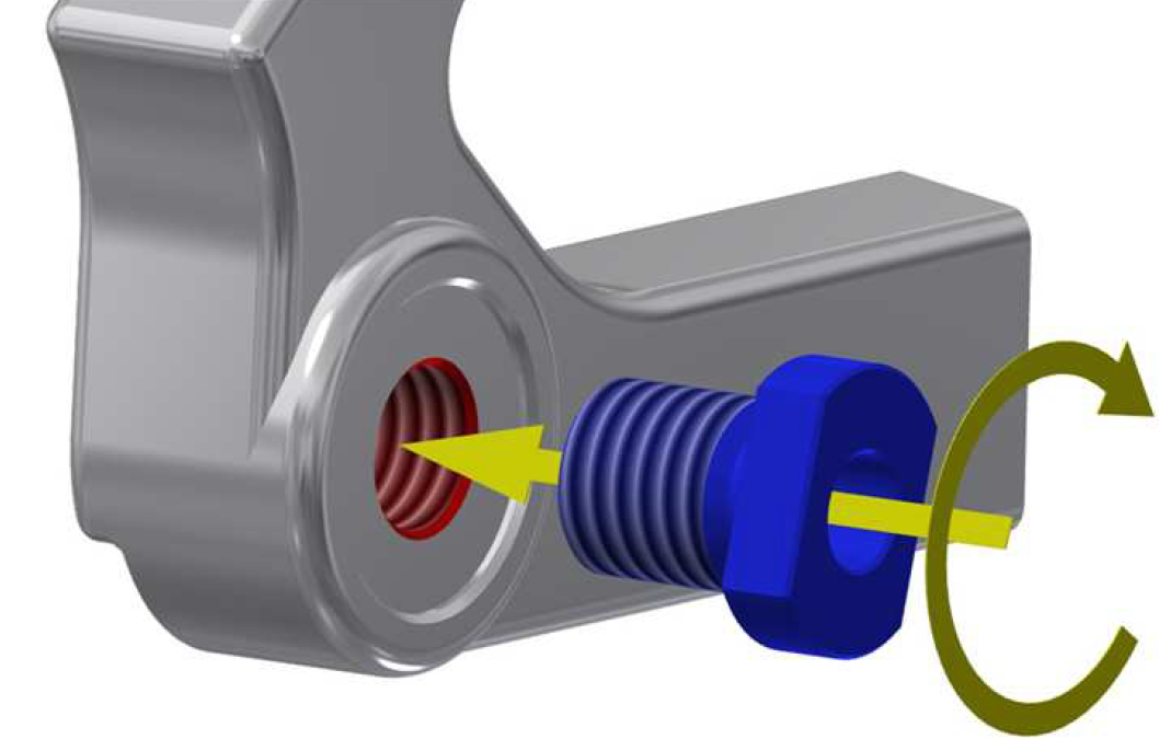
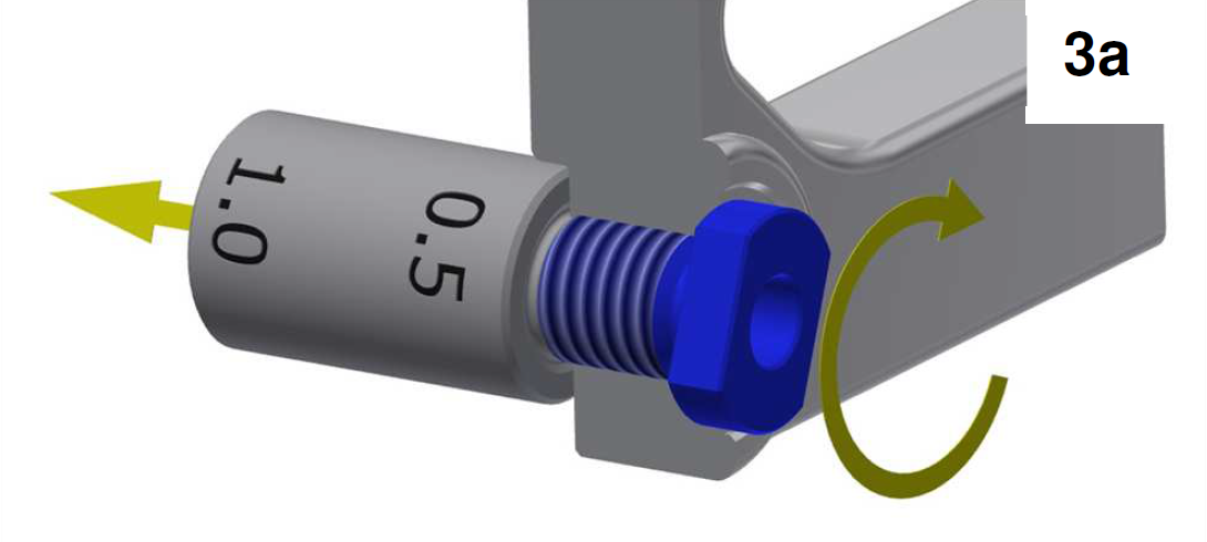
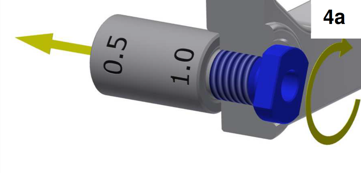
3a. Min. Play Test 0.5 mm (Dropout Thickness)
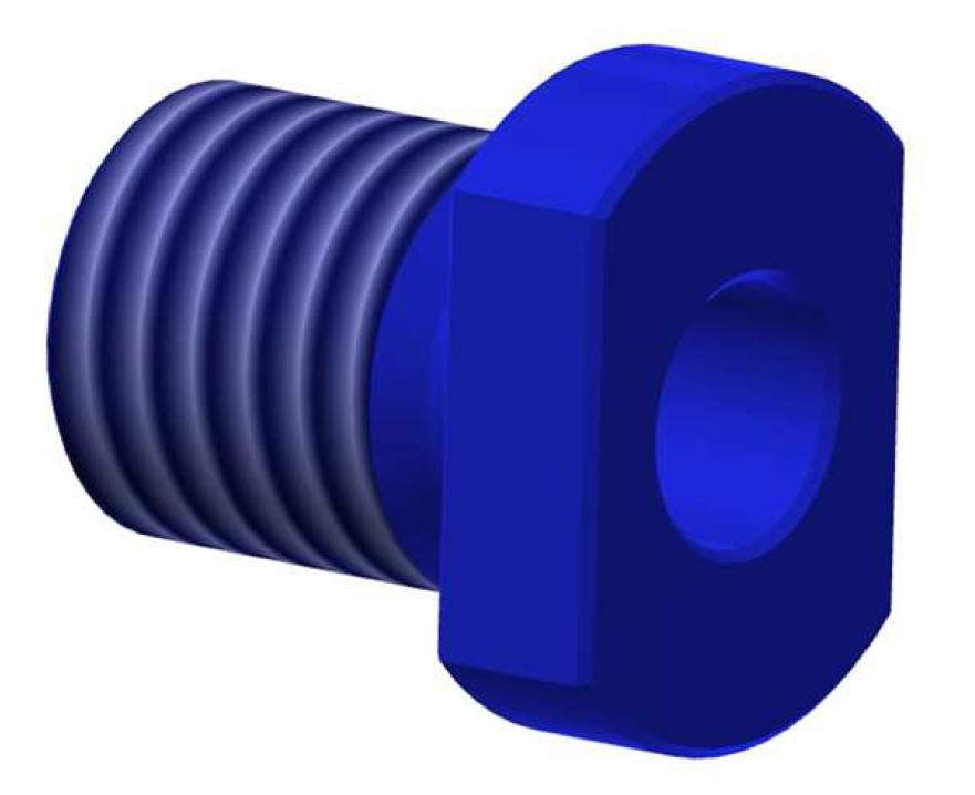
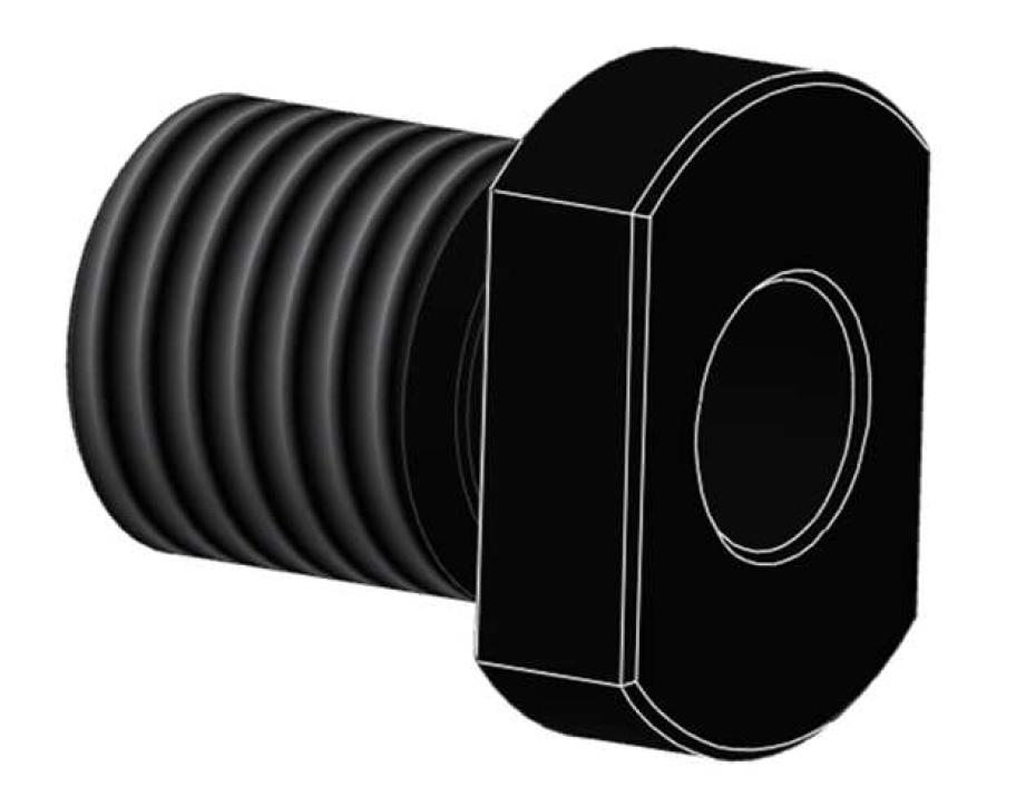
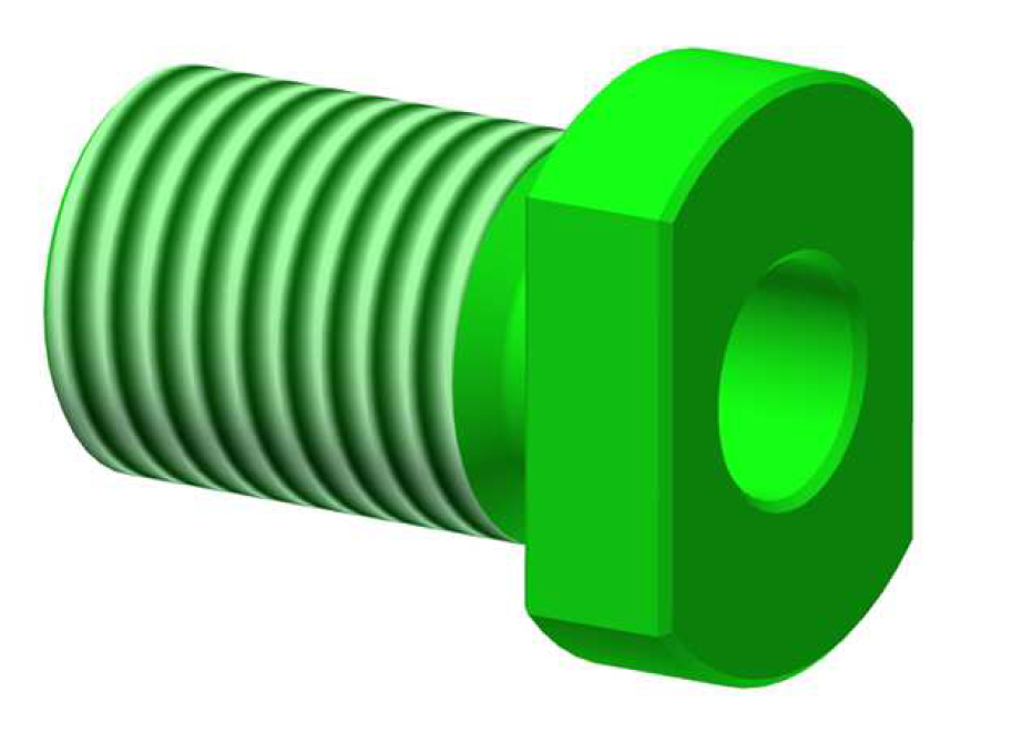
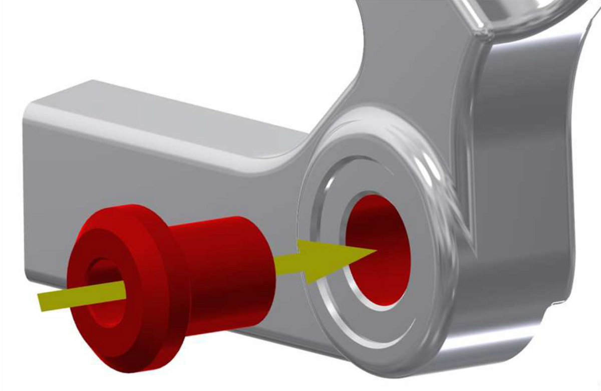
Use the 0.5 mm side of the A12 Dropout gauge. Slowly screw the A12 M12x1.75 (blue) or A12 M12x1.5 (black) threaded reduction sleeve into the dropout.
Movement of A12 dropout gauge in arrowed direction noticeable: Dropout too thin. Go to 3b) Fit Micro Shim.
Zero movement of A12 dropout gauge in arrowed direction noticeable: 0.5 mm test result OK. Proceed to 4) Max. Play Test 1.0 mm.
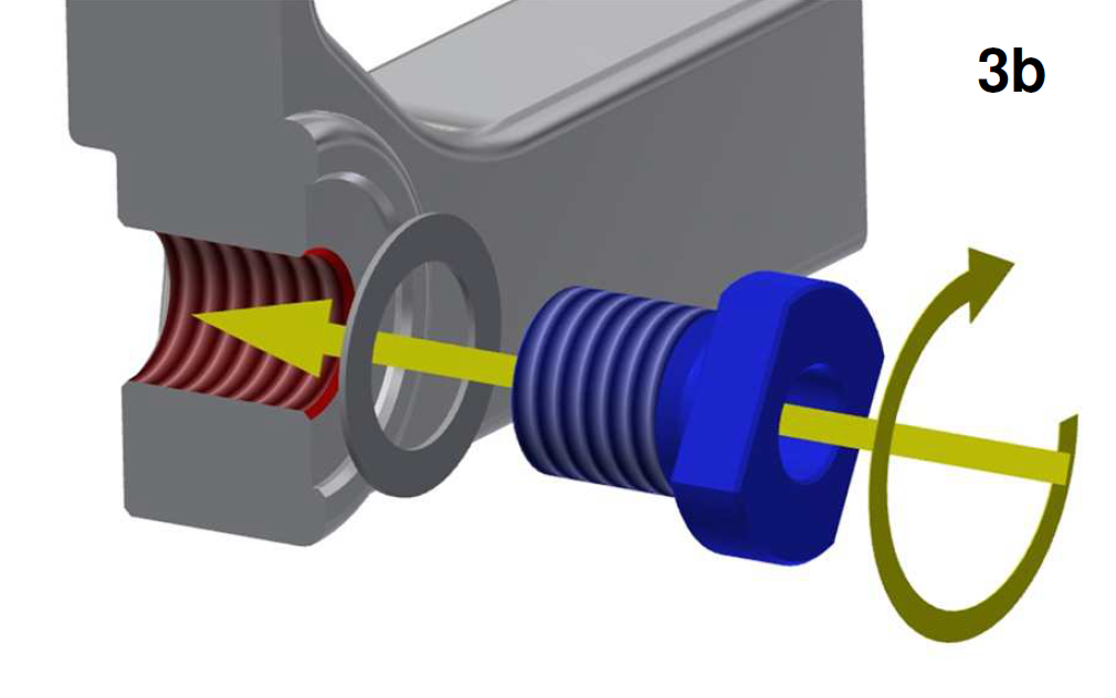
3b. Fit Micro Shim
Fit a 0.5mm micro shim between dropout and the A12 M12x1.75 (blue) or A12 M12x1.5 (black) threaded reduction sleeve. Screw the threaded reduction sleeve fully into the dropout and then back-off one full rotation.
Go to 3c) Check Fit.

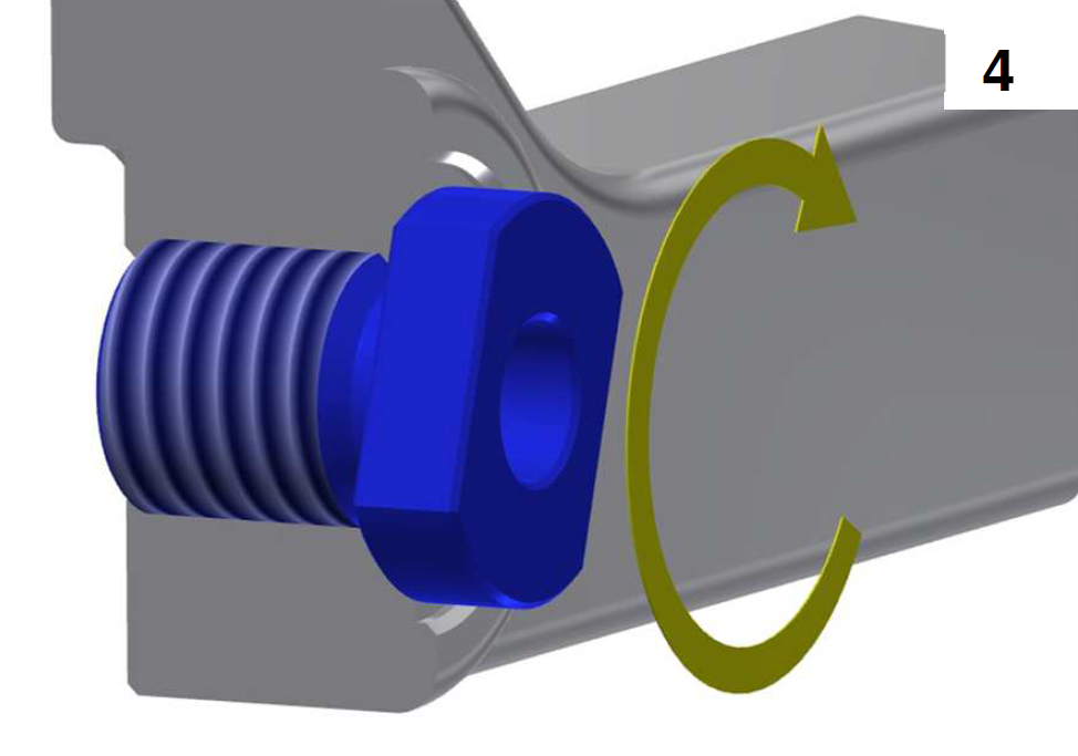
3c. Check Fit
Use the 0.5 mm side of the A12 Dropout gauge. Slowly screw the A12 M12x1.75 (blue) or A12 M12x1.5 (black) threaded reduction sleeve into the dropout.
Movement of A12 dropout gauge in arrowed direction noticeable: Go back to 3b) Fit Micro Shim, fit another micro shim and check again.
Movement of A12 dropout gauge in arrowed direction for the first time not noticeable: 0.5 mm test result OK. Testing of the righthand dropout is complete. Max. play test 1.0 not necessary. Note number of required micro shims in the order form. Proceed to second measurement process.
Use the 1.0 mm side of the A12 Dropout gauge. Slowly thread the A12 M12x1.75 (blue) or A12 M12x1.5 (black) threaded reduction sleeve into the dropout.
Zero movement of A12 dropout gauge in arrowed direction noticeable: Dropout too thick. Go to 4b) Fit Sleeve with Micro Shims.
Movement of A12 dropout gauge in arrowed direction noticeable: Test result OK. Testing of the right-hand dropout is complete.
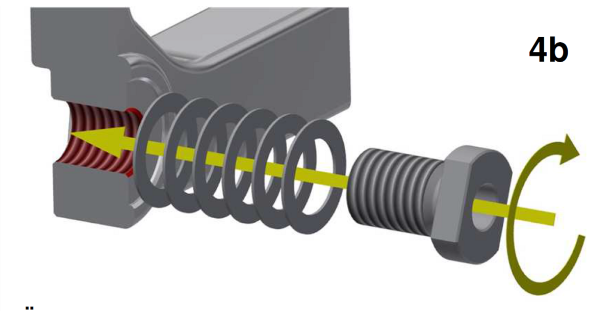
4b. Fit Reduction Sleeve with Micro Shims
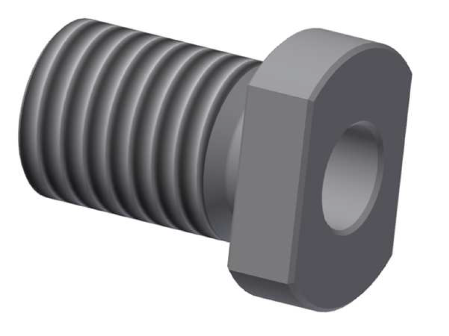
Screw the extended A12 M12x1.75 (gray) or A12 M12x1.5 (light green) threaded reduction sleeve with all six 0.5mm micro shims, fully into the dropout and then backoff one full rotation.
Go to 4c) Check Fit.
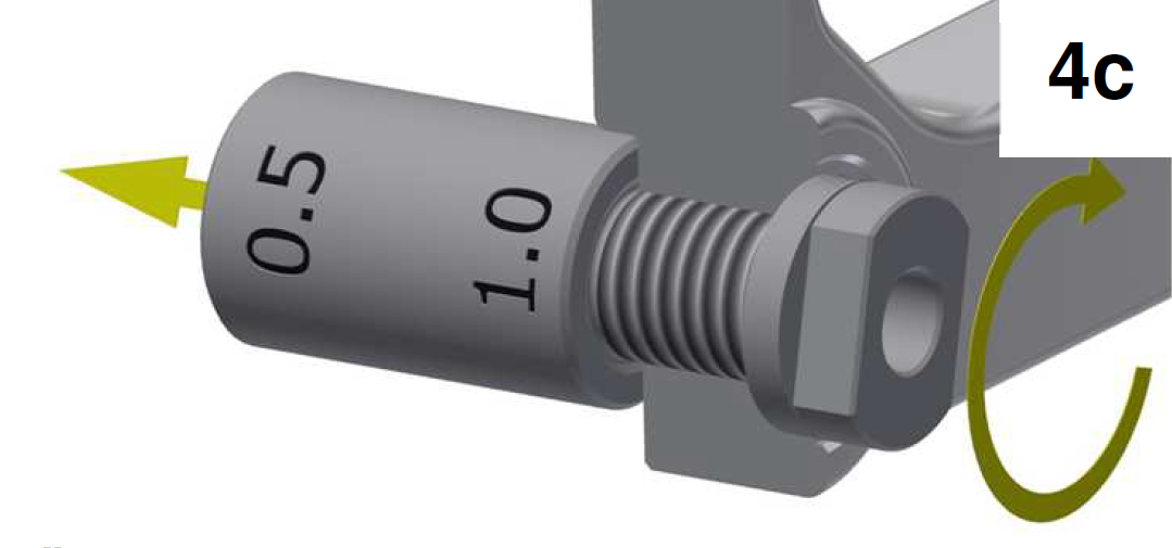
4c. Check Fit
Use the 1.0 mm side of the A12 Dropout gauge. Slowly screw the extended A12 M12x1.75 (gray) or extended A12 M12x1.5 (light green) threaded reduction sleeve into the dropout.
Zero movement of A12 dropout gauge in arrowed direction noticeable: Remove a micro shim and check again.
Movement of A12 dropout gauge in arrowed direction noticeable for the first time: Test result OK. Custom reduction sleeve required. Note number of remaining micro shims on the order form. Testing of the right-hand dropout is complete. Proceed to second measurement process.
Second Measurement Process: Measurement Gauge
Disc Brake Side (left-hand)
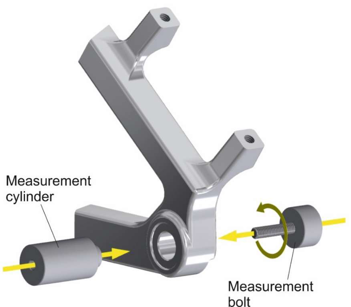
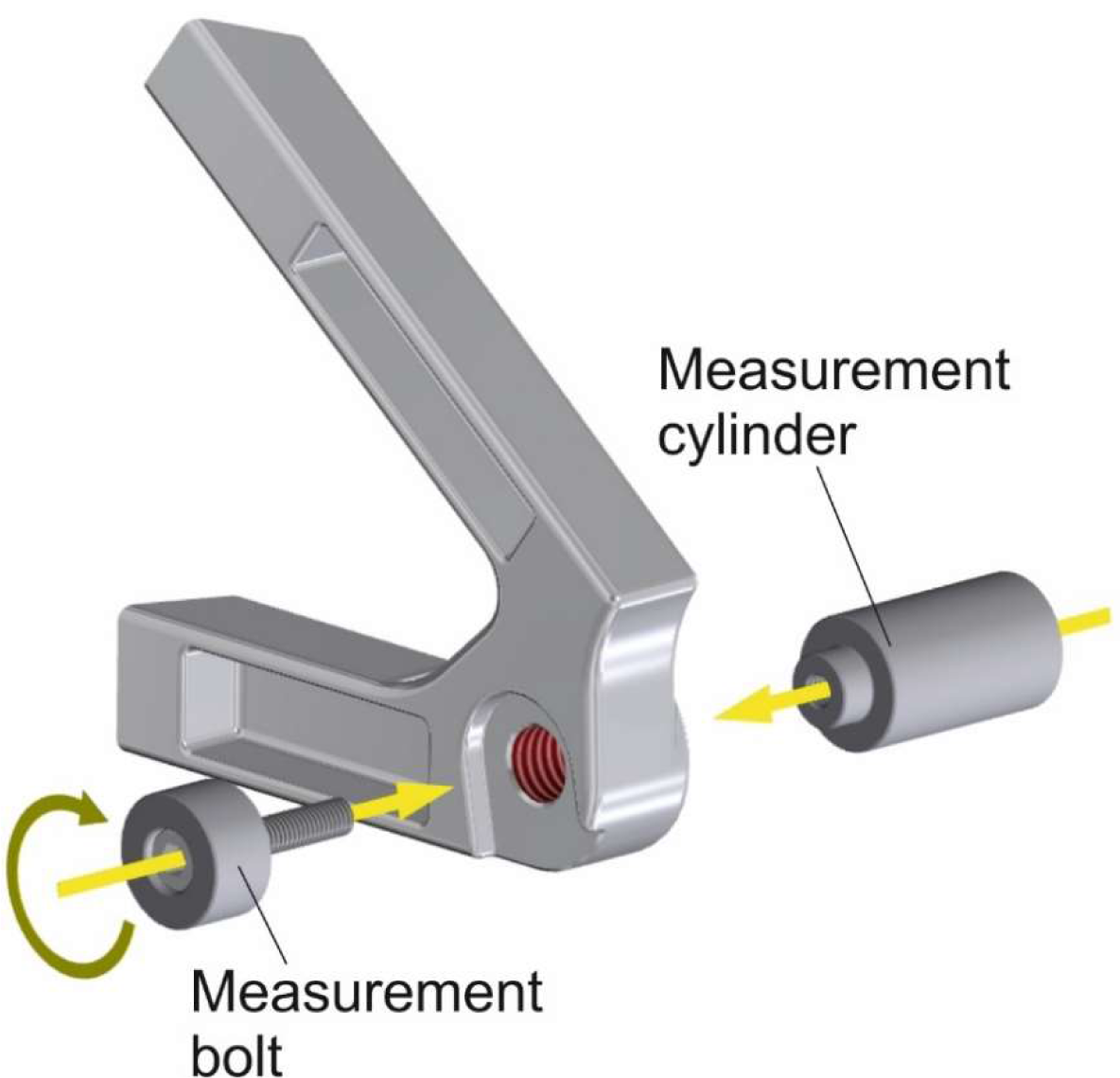
1. Attach Measurement Cylinder and Bolt
The measurement cylinder must always be positioned against the outer dropout face. The measurement bolt must always be positioned against the inside dropout face. Press the measurement cylinder against the outer face of the dropout and thread the measurement bolt into it by hand.
DT / Maxle dropouts are measured without any additional components.
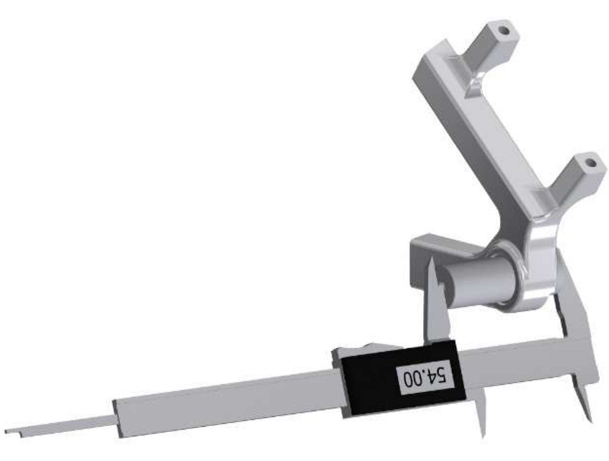
2. Take Measurement
Measure the complete length of the mounted measurement tool with a Vernier Caliper as illustrated. Enter the measured value rounded to two decimal places in the order form.
And this is how the result is to be evaluated: If the result of the measurement is less than 47 mm or greater than 57.5 mm, mounting a SPEEDHUB is unfortunately not possible.
Proceed to Sprocket Side (right-hand).
Sprocket Side (right-hand)

2. Take Measurement
Measure the complete length of the mounted measurement tool with a Vernier Caliper as illustrated. Enter the measured value rounded to two decimal places in the order form.
And this is how the result is to be evaluated: If the result of the measurement is less than 47 mm or greater than 57.5 mm, mounting a SPEEDHUB is unfortunately not possible.