Twist shifter until 2010

What you can expect to find on this page

A new twist shifter has been available since 2011. Here we write how the assembly worked with the old shifter until 2010.

The assembly of the current twist shifter can be found here.

Fitting of the twist shifter pre 2010

The twist shifter works with two shift cables. When the twist shifter is rotated forward (direction gear #14), than the rear shift cable 14 is pulled. When the twist shifter is rotated backward (direction gear #1), than the front shift cable 1 is pulled.

Twist shifter parts:

A Clamp screws
B Cable stopper 1
C Cable stopper 14
D Clamp ring
E Twist shifter casing
F Grip rubber

The cable stoppers 1 and 14 are fitted, so that the shift cables run parallel out of the twist shifter. The cable stopper 1 has its cable exit hole directly in the middle. The cable stopper 14 has its cable exit hole positioned to the side.

Slide the twist shifter onto the right hand side of the handlebars (diameter 22.0mm - 22.3 mm) and turn the shifter casing, so that the two cable stoppers sit evenly on both sides of the brake lever.

Remove the clamp screws (M5x8 - 2.5mm allen key), lightly grease them and refit them to clamp the twist shifter to the handlebars (tightening torque: 1Nm / 8 in.lbs.).

Remove cable stopper 1. Twist the grip rubber, so that the cable nipple seat of cable run 14 becomes visible (at the position of gear #2).

Pointer

It is possible to mount both of the gear cables through the same hole of one of the cable stoppers.

Insert the first shifter cable (shifter cable 14) into cable run 14 from below until cable appears out of cable stopper 14. Pull the cable until the nipple sits firmly in the cable nipple seat.

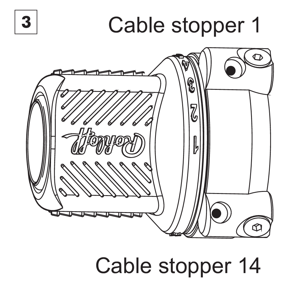
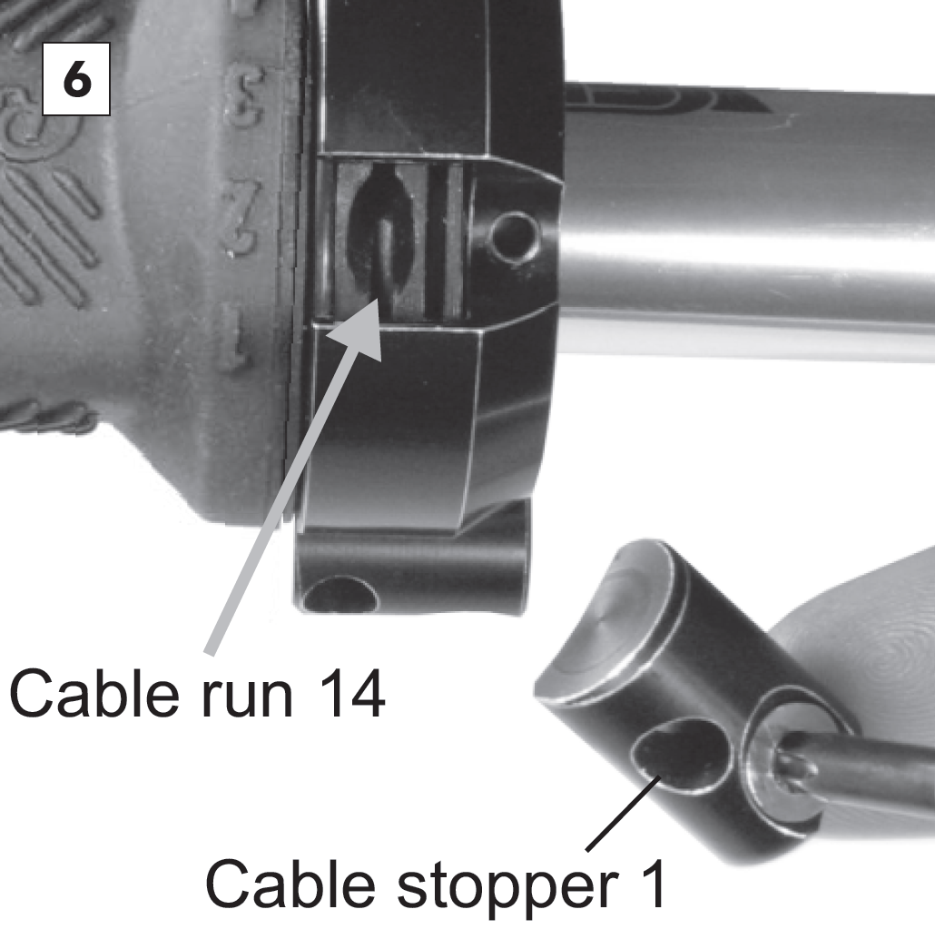
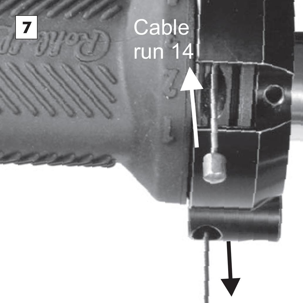
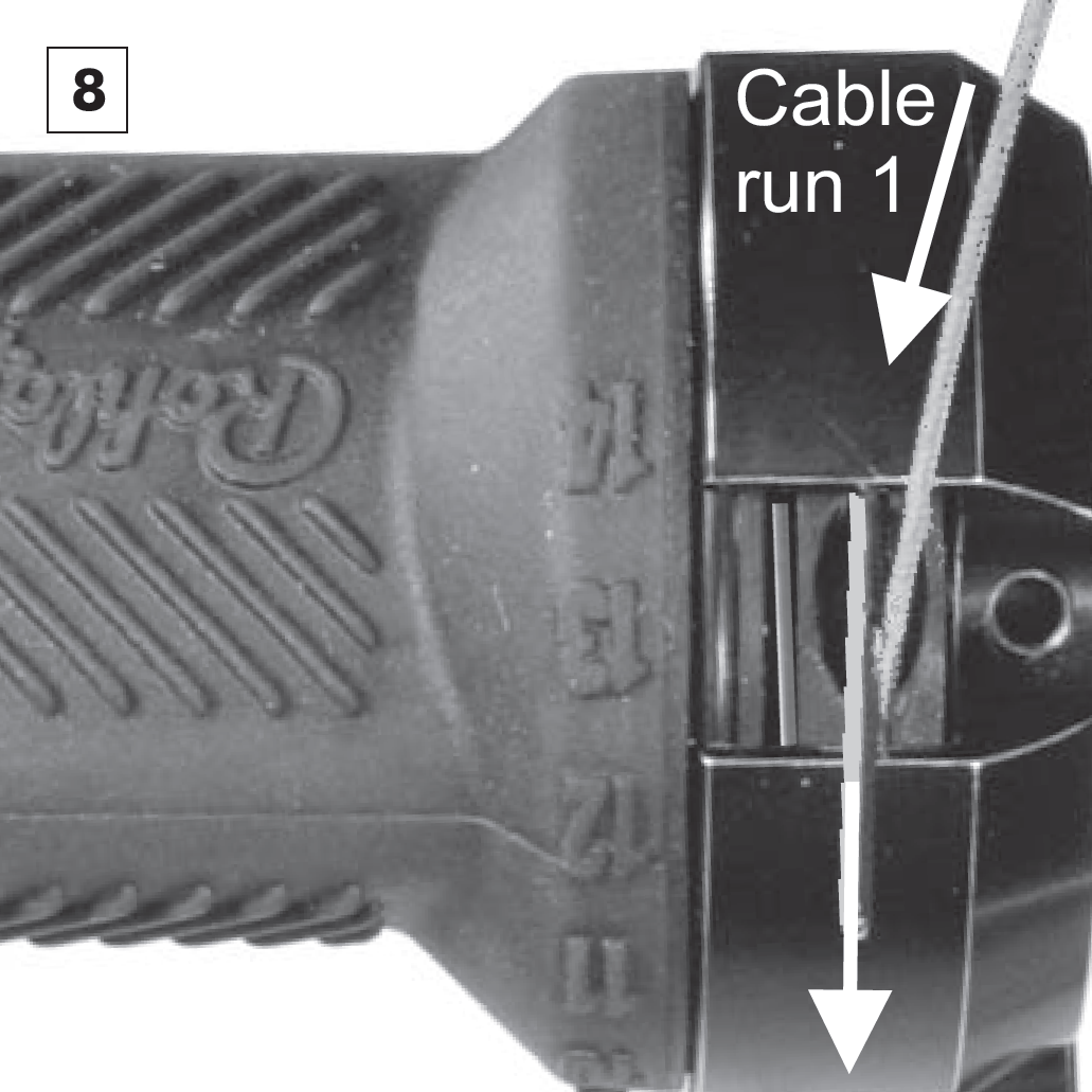
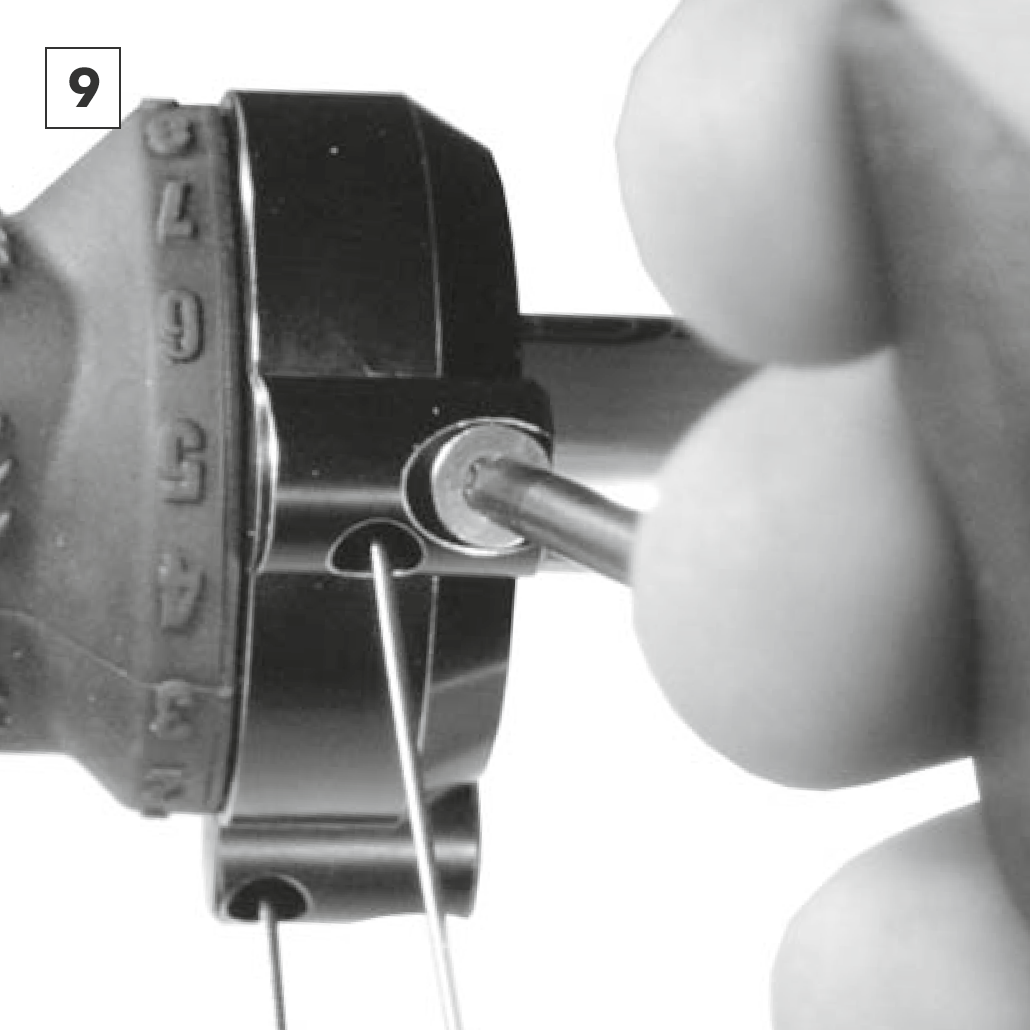
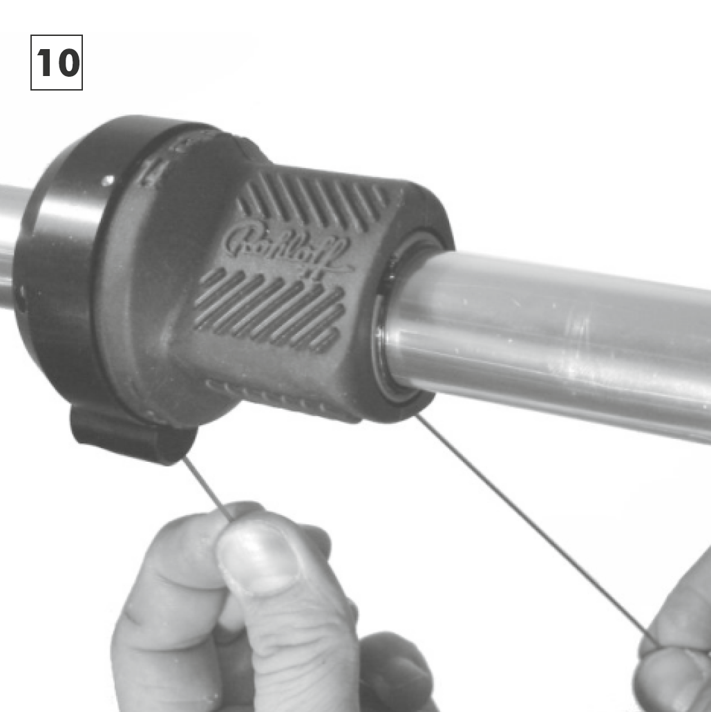
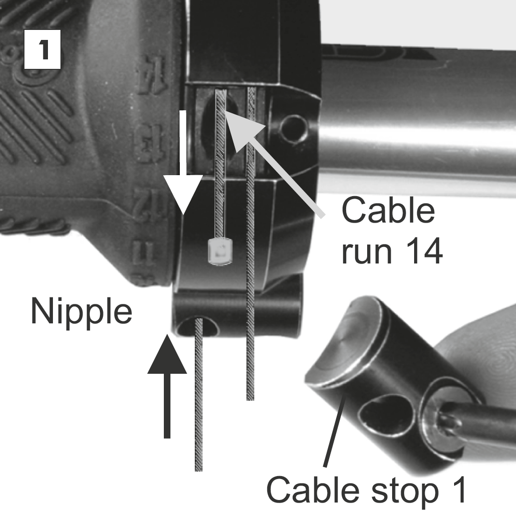
Twist the grip rubber, so that the cable nipple seat of cable run 1 becomes visible (at the position of gear #13). Insert the second shifter cable (shifter cable 1) into cable run 1 from above until the cable appears out of cable feed 1. Pull cable until the nipple sits firmly in the cable nipple seat.

Insert shifter cable 1 into the cable stopper 1 that was removed. Refit cable stopper 1 to the twist shifter casing (M4x16 - Torx TX20, tightening torque: 3 Nm / 25 in.lbs.).

Now control that the twist shifter rotates freely by grabbing both shifter cables and pulling them in turn, so that the grip rubber rotates from just before the number 1 to just past number 14.

The flaired end to the liners H must be mounted between the cable housing G and the housing caps J at the twist shifter. This is important to prevent the liner from being pulled into the cable run itself

It may be necessary to adjust the angle of the twist shifter now that the cables are fitted, so that the cables don't touch the brake lever.

Achtung

Mount the cables dry, without the use of grease or oil.

Attention

Clamp the twist shifter only so tight that it is not possible to move the twist shifter casing by hand.

Changing the grip rubber

Pointer

The shifter cables have to be removed from the twist shifter first before it is possible to replace the rubber grip. Before the shifter cables are removed, the ends that were clamped in the female connectors (internal gear mech) or the cable pulley (external gear mech) must be cut so that the frayed ends of these cables do not damage the nylon liners when being removed.

Remove cable stop 1 and rotate the twist shifter until the nipple of shifter cable 14 can be seen. Pull the cable out of the twist shifter. Repeat this process for the removal of  shifter cable 1.

With a flat screwdriver, remove the safety ring. The rubber grip can now be removed. Clean the twist shifter housing.

Lightly grease the twist shifter housing. The arrowed “O  ring” must also be lightly greased and checked that it is sitting in the correct position before remounting

The safety ring can now be remounted. Check that  the twist shifter rotates smoothly and freely. Refit new shifter cables (see chapter "Mounting", paragraph 6. "Twist shifter").

Tip

Should only the rubber grip need to be replaced. Firstly shift into gear #14. Disconnect the Bayonet Connectors or the External cable box. Screw both of the cable adjusters completely in and remove the two screws on the cable stops of the shifter. Remove the safety circlip and slide the complete rubber grip out of the shifter housing and off of the handlebars. Hook both the cables out of their seats in the rubber grip, transfer these and re-hook them into the new, lightly greased rubber grip (Art.N° 8201). Wind these cables roughly 3/4 (270°) around the new grip in their respective runs and slide this new complete unit back inside the shifter housing and refit both of the cable stops. Replace the safety circlip and lightly test the shifter functions correctly. Reconnect the Gear mech in gear #14.