Hub Types
SPEEDHUB Variations
Even though the range of bicycles available nowadays is incredibly varied, the Rohloff AG has a SPEEDHUB to fit almost every frame.
The construction of the SPEEDHUB is based around a modular system. The classic SPEEDHUB versions are constructed for a 135mm O.L.D. and available with a choice of quick-release (CC) or threaded axle (TS). In the past years, the Rohloff AG have extended the SPEEDHUB range to remain compatible with modern, alternative mounting options. As such, we are pleased to confirm that SPEEDHUBs are currently available to fit numerous frame spacings from 135mm to 197mm for fatbikes with 12mm thru axle system.
![[Translate to en:] Schwarz Eloxiert](/fileadmin/_processed_/e/4/csm_8027Z_525f489108.png "[Translate to en:] Schwarz Eloxiert")
![[Translate to en:] Rot Eloxiert](/fileadmin/_processed_/b/c/csm_8026_06_1aa66f41f6.png "[Translate to en:] Rot Eloxiert")
![[Translate to en:] Aluminium poliert](/fileadmin/_processed_/2/3/csm_8025_01_4787a337ce.png "[Translate to en:] Aluminium poliert")


12mm, thru-axle compatible (A12)
Special adapters permit compatibility with 12mm thru-axle frames.
Torque anchoring apparatus
Frame construction is an art-form. As with every art form, the artist/fabricator wishes to leave their signature and this is often achieved through the dropout design. The Rohloff AG are pleased to offer 4 different methods of anchoring SPEEDHUB output torque to the bicycle frame, so that we remain compatible with nearly all dropouts styles available to a frame fabricator.


Gear Mechanism
Further options; our ultimate goal is to retrofit as many bicycles as possible with a SPEEDHUB transmission. Two different gear mechanisms are thus available to help us achieve this goal. An internal gear mech (which sits inside the dropouts, directly on the gear-unit) and an external gear mech (where a cable box is located outside of the dropout away from brake rotors). The internal gear mech not compatible with disc brake versions.


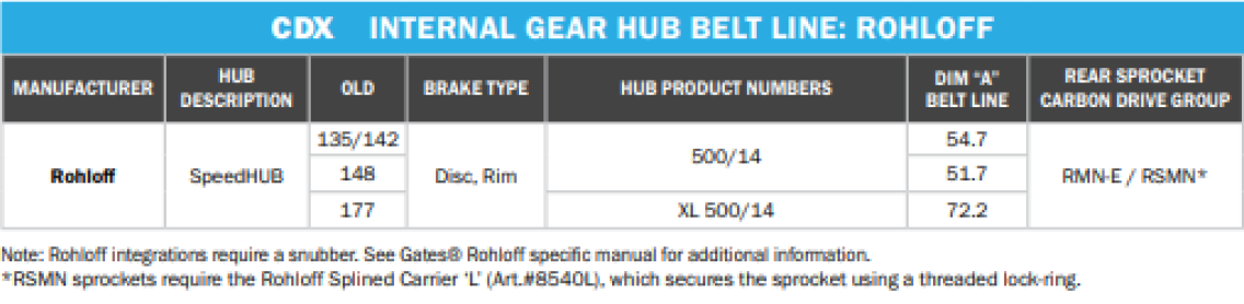
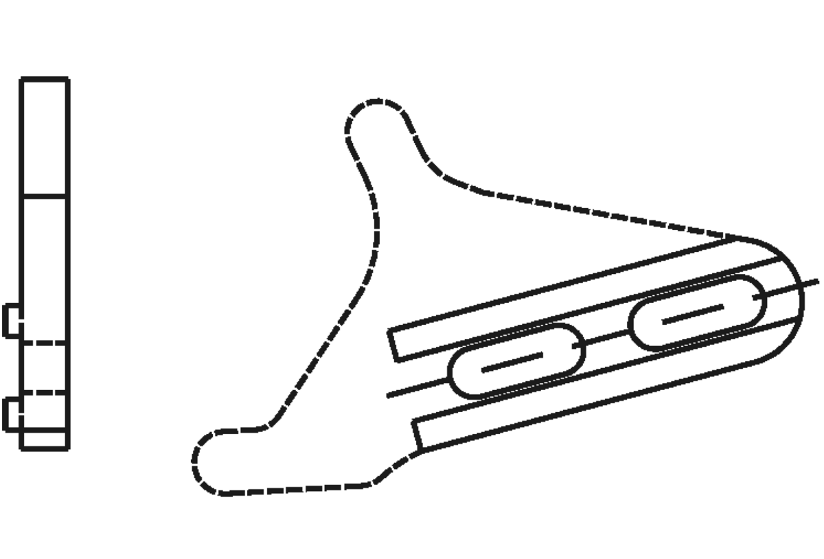
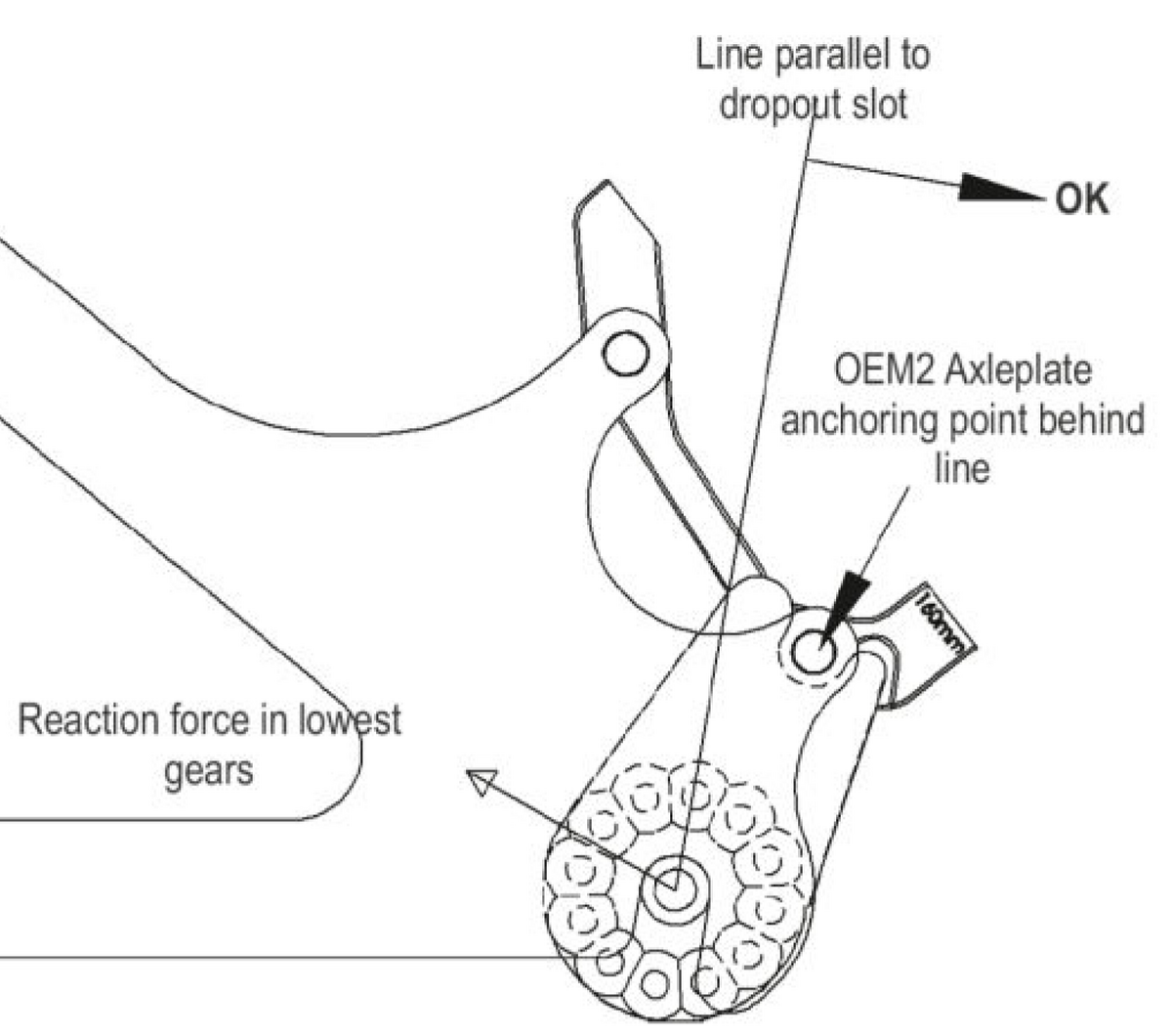
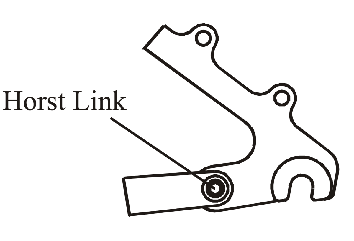
Version 1: OEM Specific Left-hand Dropout
This version is particularly suitable for rear suspension frames. In order to compensate for the altering chain length as the rear triangle moves, an external chain tensioner will also be required. Both CC (hollow, quick-release) and TS (M10x1 threaded) axle versions can be used with this style dropout.
Left-hand dropout mounted with SPEEDHUB 500/14
Chain Tensioner or eccentric BB required.
All necessary measurements can be found on the accompanying technical drawing OA11.
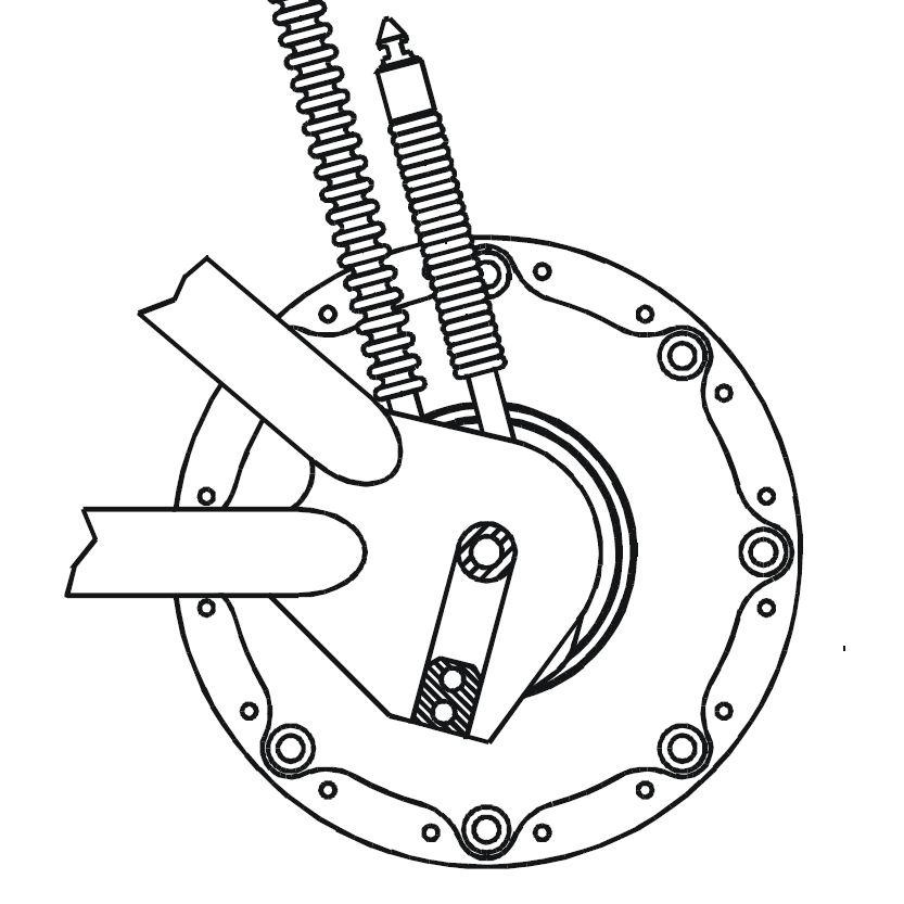
Version 2: Adjustable OEM dropout
This version consists of two basic elements: - the dropout (brazed/weldet to the main bicycle frame) and the dropout insert which is bolted to it. This version is typically used on hardtrail bicycle frames where the chain/belt length does not alter.
The chain tension is altered by moving the dropout insert back and forth, within the actual brazed dropout section. To tension the chain, one simply loosens the securing bolts and pulls the wheel backward until the desired tension is achieved. The bolts are then tightened again to prevent the wheel moving forward under load. The only thing one really needs to check, is that the wheel remains central between the chainstays.
The dropouts may also be machined/drilled and tapped, for mounting a luggage rack and fender.

Steel or aluminum cluster (seat), right-hand side
The exact dimensions are shown on the technical drawing OA04.
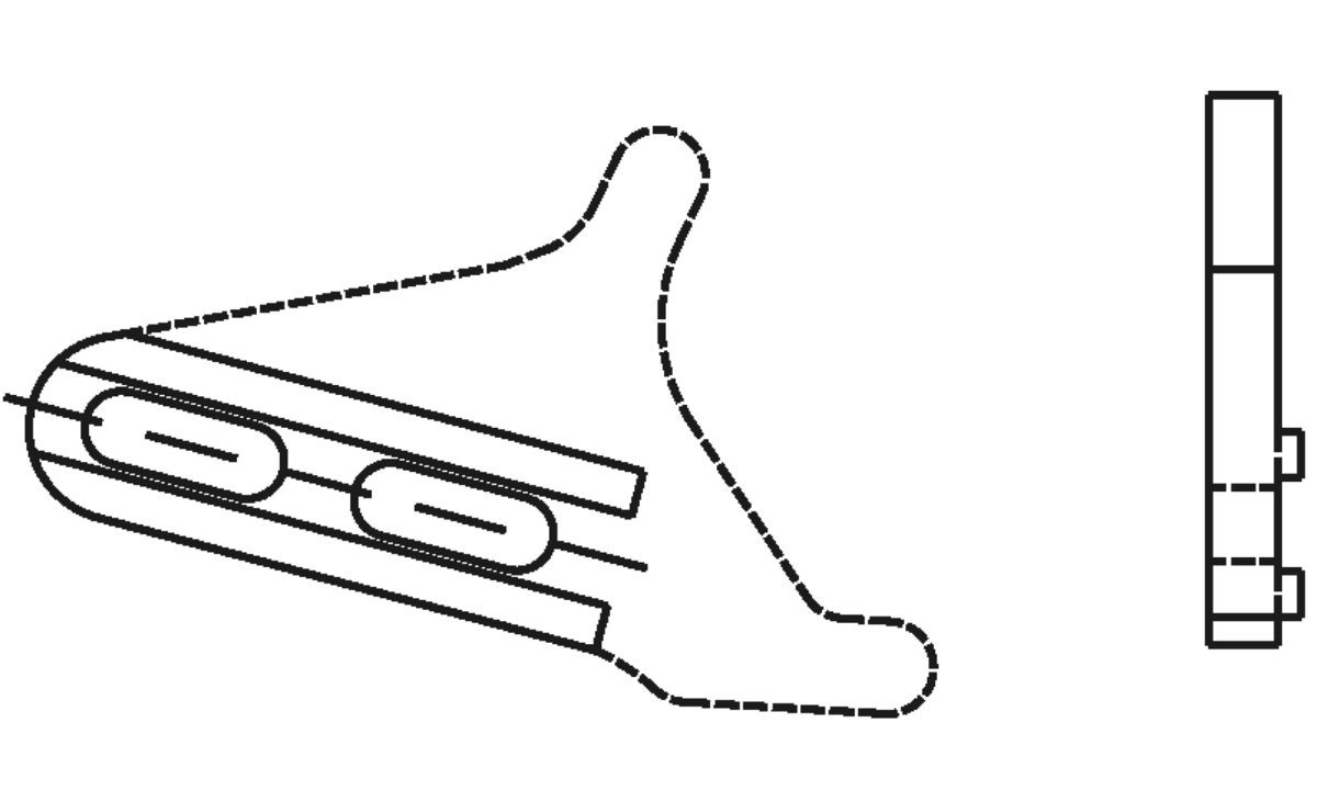
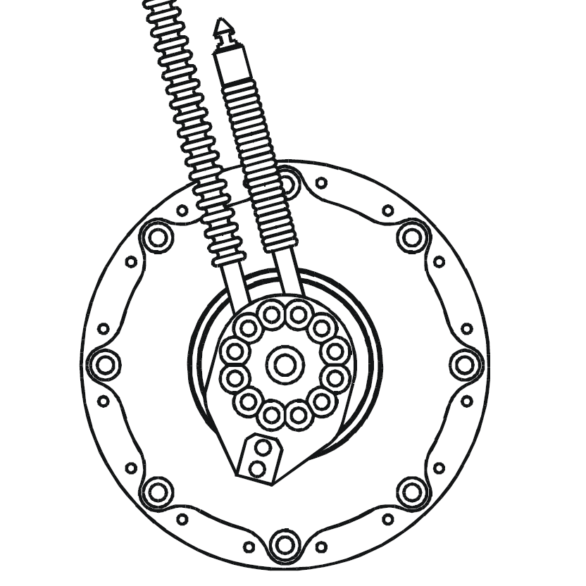
Left-hand dropout, technical drawing OA13
This and the next image show the left-hand & right-hand dropout inserts designed solely for SPEEDHUB 500/14 use.
Right-hand dropout, technical drawing OA14

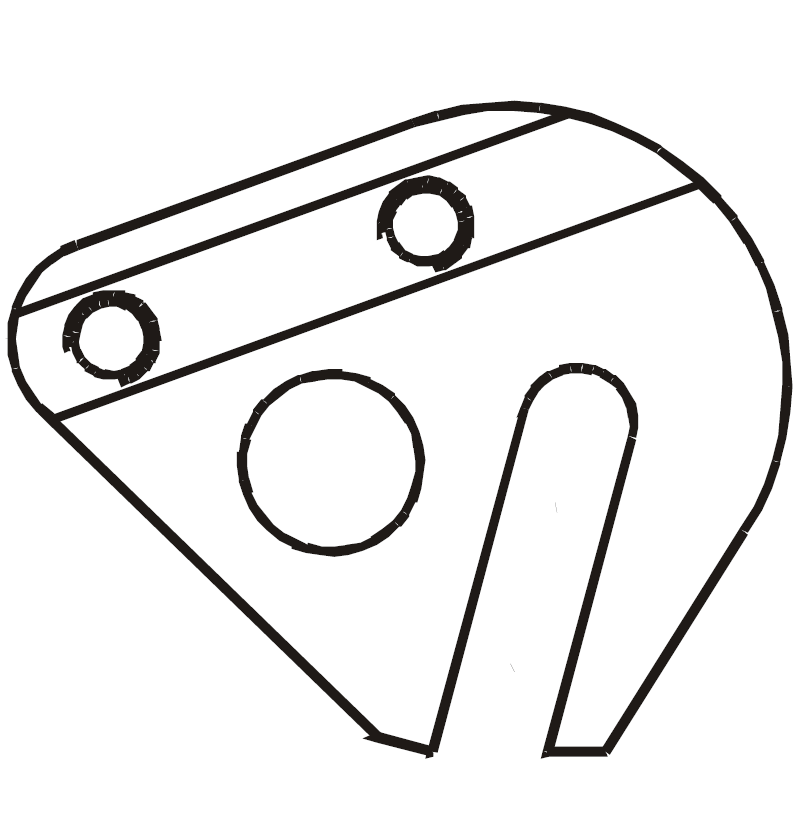
Right-hand dropout with derailleur hanger, technical drawing OA28
This dropout also allows the mounting of a rear derailleur. It can therefore be used with the Rohloff SPEEDHUB 500/14 or a conventional derailleur system.
The dropout as in shown Fig. 8 must be fitted to all full suspension bikes where the chain length changes.
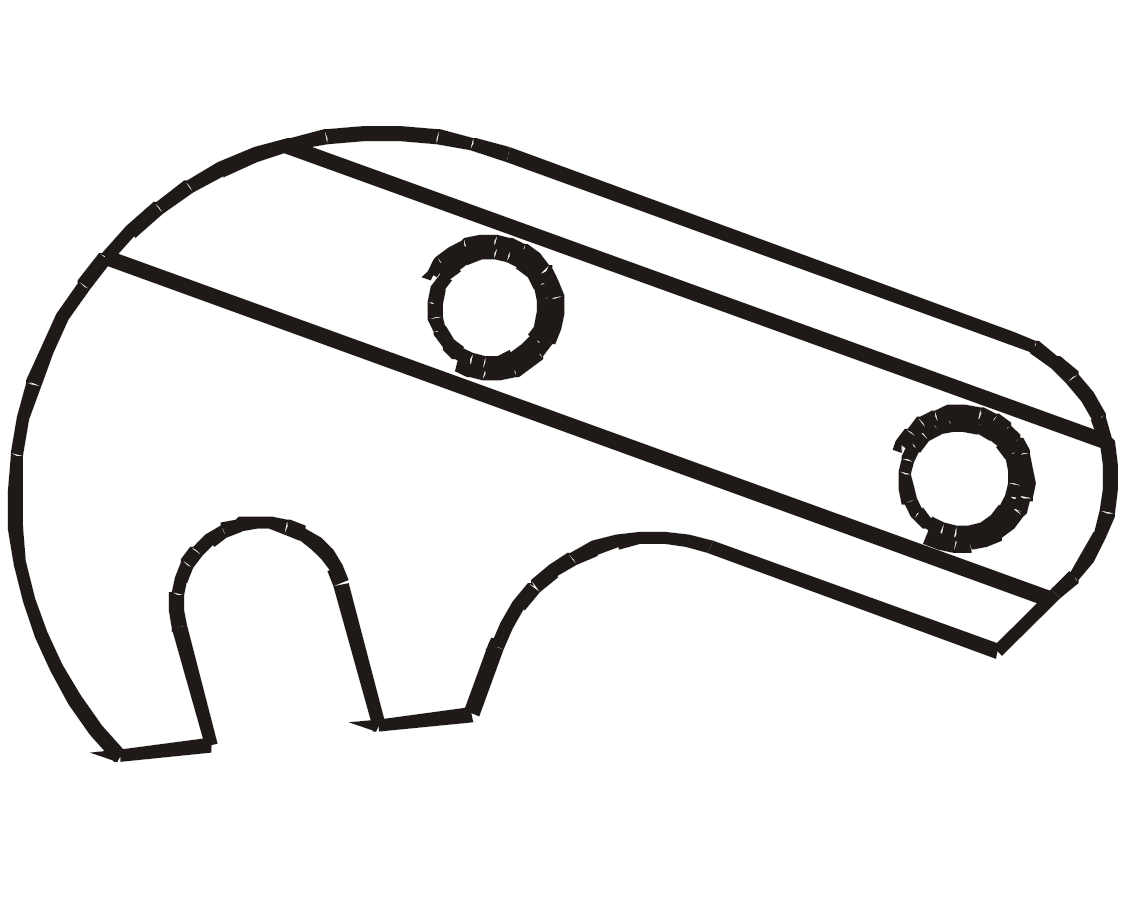
OEM dropout insert (DB), disc brake mount on left-hand side, technical drawing OA25
With regards to the installation of a disc brake, this dropout will be necessary.

[hidden]
CNC-Formteile
Lauble & Fichter Rohloff Ausfallenden sind hochwertige CNC gefräste Teile, die der Qualität der Speedhub 500/14 gerecht werden. Es gibt sie in verschiedenen Ausführungen. Informieren Sie sich auf der Webseite des Herstellers
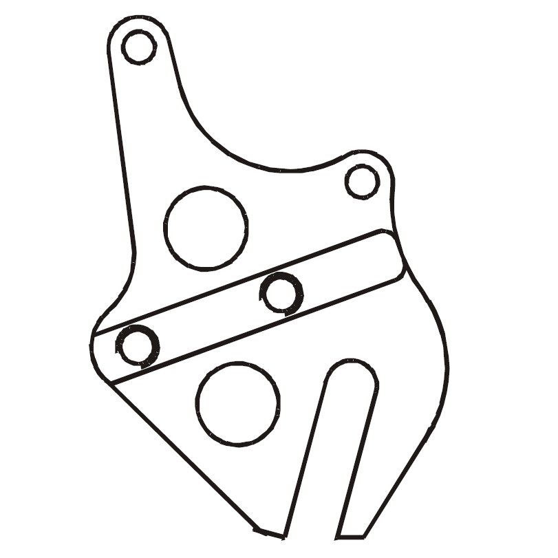
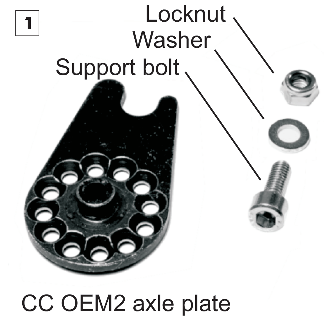
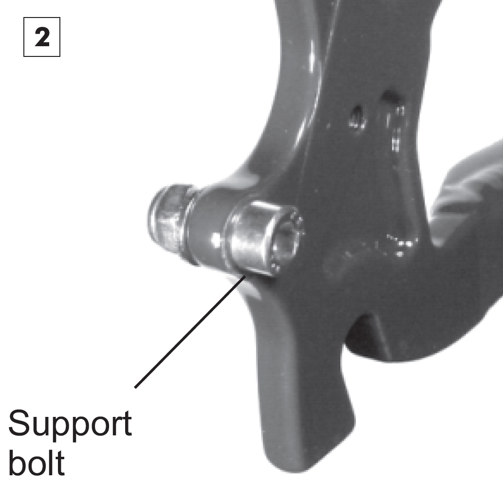
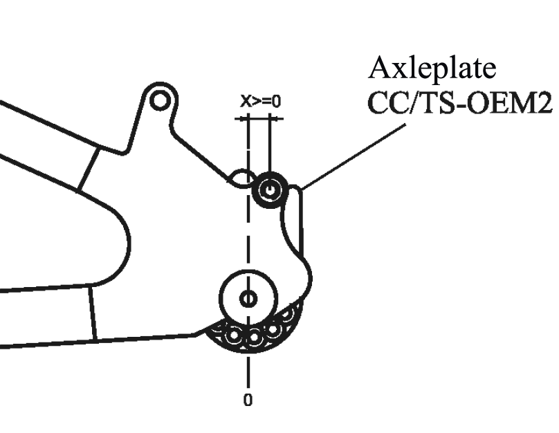
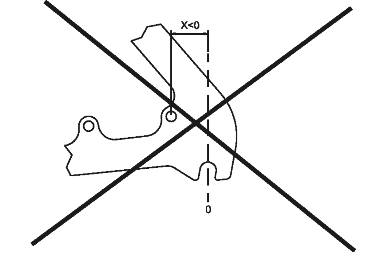
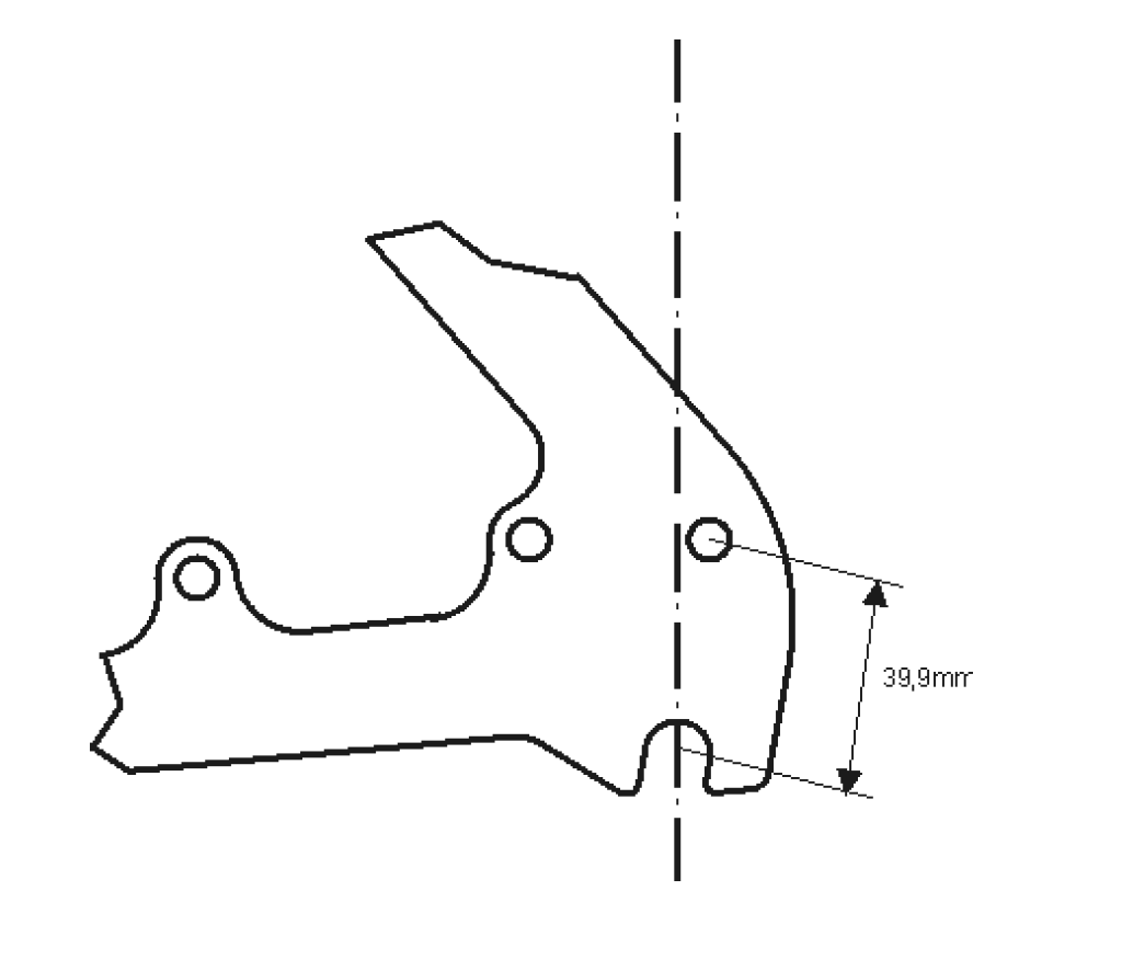
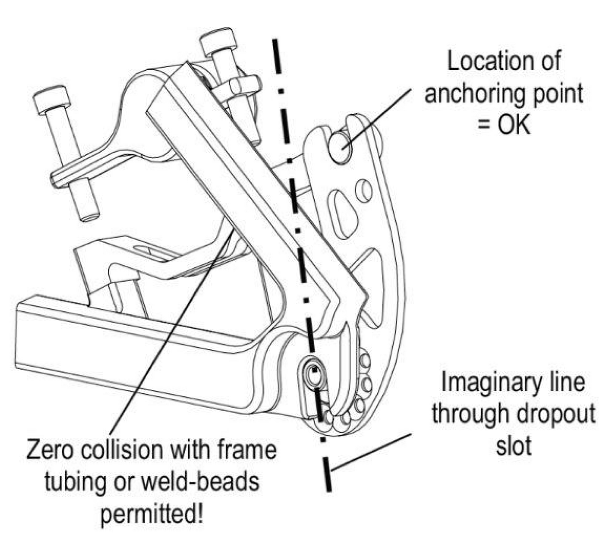
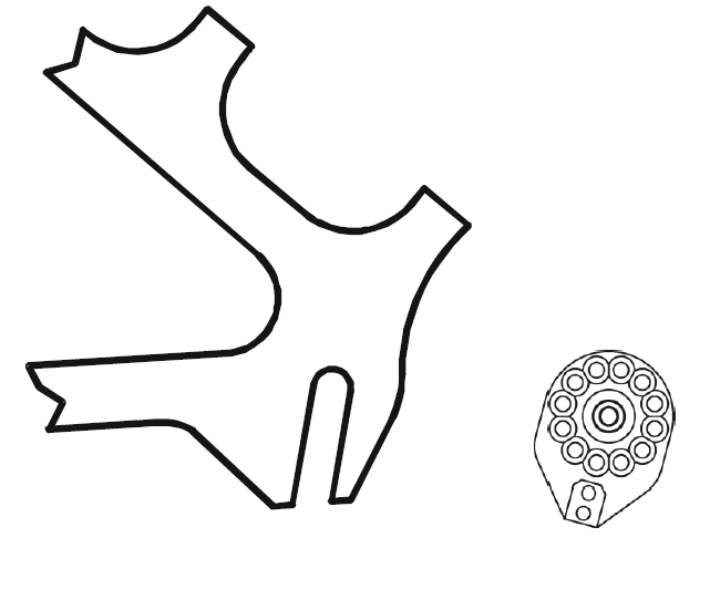
Version 3: OEM2 with Support Bolt
The OEM2 axle plate can be used in two versions with a support screw:
- The frame has a disc brake mount, but no disc brake is installed. Use M6 screw.
- The frame has an M5 luggage carrier thread and the distance to the center of the axle is 39.9 mm. Use OEM2 adapter with M5 screw.
Both versions have in common the position behind the imaginary line through the axle slot. In addition, both need the distance to the center of the axle of 39.9 mm. The exact dimensions are shown on the technical drawing OA47.
Frames with International Standard (IS-1999) disc brake mounts.
If the disc brake mount on the frame is used to anchor the SPEEDHUB torque, then this area must have the following dimensions.
If the above dimensions are kept and the frame material is faultless, the manufacturer may safely install the Rohloff SPEEDHUB 500/14, as described here for version 3 and version 4. The technical OEM2 data sheet must be referred to when using this product!
Furthermore, it is necessary to grant retailers permission to use this method of supporting the output torque produced by the Rohloff SPEEDHUB 500/14! You can download the corresponding form from the following link:
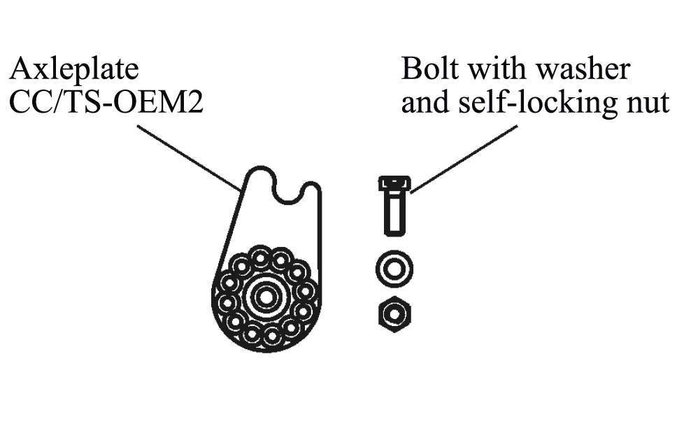
The OEM2 axle plate can also be used when an additional hole is positioned in the dropout behind a vertical line through the axle. This hole must accept an M6 bolt or an M5 bolt in combination with our M5-OEM2 adapter (Article #8552).
Ideally, a drilled & tapped luggage/fender mount hole can be located in the correct position (39,9mm) from the axle center and thus ensuring each frame is SPEEDHUB compatible using Art.#8552, even if not primarily sold with the SPEEDHUB option.

Adapter OEM2 for M5 screw (Article No. 8552)
See also axle plate accessories in our B2B shop.
Important: An M5 cylinder head is only 8 mm in diameter, therefore an M5 screw must not be used without the OEM2 adapter with a diameter of 10 mm (Article No. 8552).
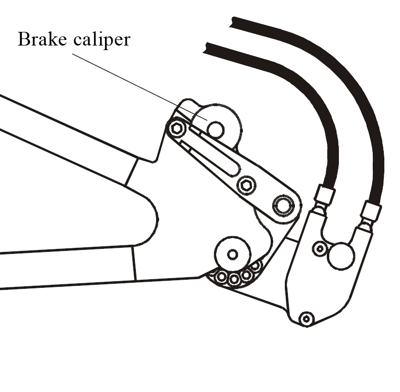
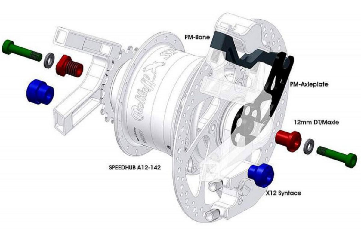
Version 4: OEM2 with Disc Brake
OEM2 axle plate; bicycle frame with disc brake mounts of International Standard (IS-1999)*, and a mounted disc brake.
Dropout with disc brake mount (International Standard IS-1999): If a disc brake is mounted, the torque can be anchored to the frame using the CC OEM2 or TS OEM2 axleplate, in conjunction with either the SPEEDBONE or Monkeybone.
*Dimension information: Dropouts built to International Standard IS-1999 feature 16.3mm distance between the inner face of the dropout and the brake disc itself.

Mounting the OEM2 axleplate with SPEEDBONE and External Gear Mech.
See technical drawing OA79 in our drawing set.

Frames with International Standard (IS-1999) disc brake mounts.
If the disc brake mount on the frame is used to anchor the SPEEDHUB torque, then this area must have the following dimensions.
If the above dimensions are kept and the frame material is faultless, the manufacturer may safely install the Rohloff SPEEDHUB 500/14, as described here for version 3 and version 4. The technical OEM2 data sheet must be referred to when using this product!
Furthermore, it is necessary to grant retailers permission to use this method of supporting the output torque produced by the Rohloff SPEEDHUB 500/14! You can download the corresponding form from the following link:
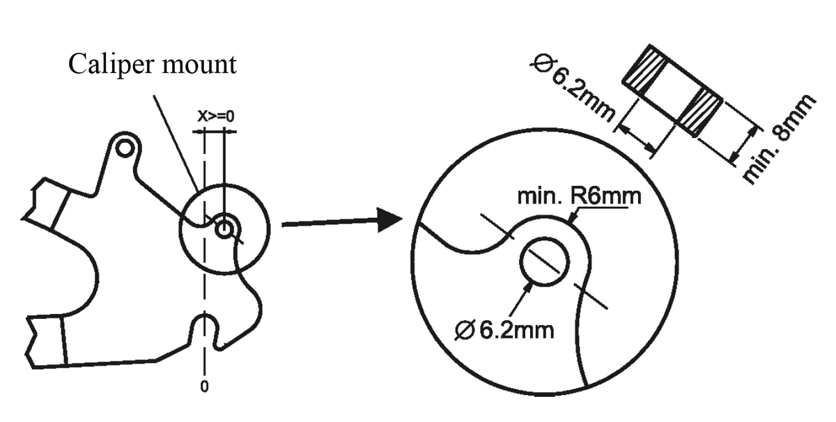
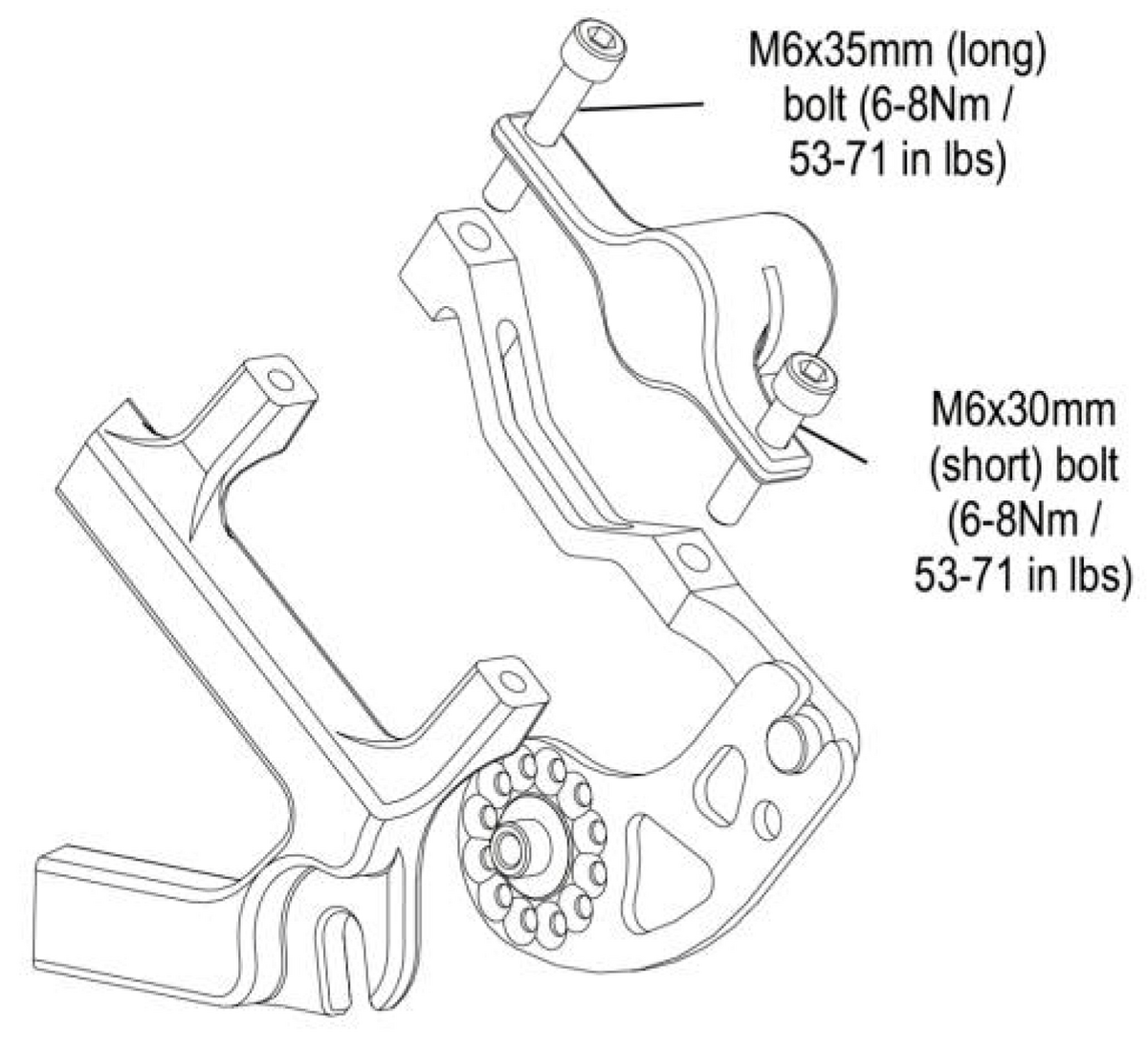
Version 5: Postmount direct
Frames with a Postmount (PM) direct caliper mount: The Rohloff PM Axleplate in combination with the PM Bone offers an alternative method of anchoring the hub torque to frames with a 135mm, 142mm, 148mm, 170mm or 177mm spacing. The PM Axleplate/PM Bone combination is recommended when mounting a SPEEDHUB to frames with an integrated Postmount direct caliper mount. The threaded holes of the direct caliper mount will be used to secure the PM Bone.
See also the corresponding chapter in our Speedhub manual.
Version 6: 12mm Thru-axle Frames (optional Sram UDH)
The installation conditions for 12mm thru axle frames can be found in our compatibility check for equipping a 12mm thru axle frame (142/148/177/197mm) with a Rohloff SPEEDHUB A12 hub: just click here

Gear Mech
E-14 Shifter Unit
The Rohloff E-14 is the electronic shifting system for e-bikes combined with the Rohloff SPEEDHUB 500/14. You can find detailed information about the Rohloff E-14 here in our manual.
The Rohloff E-14 shifter unit, combined with the Rohloff SPEEDHUB 500/14, works in unison with Bosch and Panasonic FIT eBike transmissions to provide an optimally coordinated shift between gears.
This in turn increases both the rider comfort, safety and battery range while simultaneously drastically reducing the wear of all bicycle transmission components.
Brake disc magnet for speed sensor
Rohloff E-14 magnet for brake disc
We offer a magnet holder for speed sensors integrated in the dropout.
- Magnet position: R 32mm / Ø 64mm
- mounted in cutout of the brake disc
This is e.g. compatible to Bosch MY21 speed sensors
Detailed drawing in the OEM Drawings set (OA126).
Mounting: Sensor Magnet to be mounted in brake rotor prior to assembly
- Art.No. 8817 – Sensor Magnet for Rohloff brake rotors t2.0mm
- Art.No. 8818 – Sensor Magnet for Rohloff brake rotors t1.8mm
- Art.Nr. 8819 – Sensor Magnet for Rohloff brake rotors t2.3mm petrol
External Gear Mechanism
Spokes / Rims
Spoke lengths
The Rohloff SPEEDHUB 500/14 is available with either 32, or 36 spoke holes forming a hole diameter of 100mm. 26“-wheels therefore, require shorter spokes which are slightly more difficult to source.
The large spoke hole diameter of the SPEEDHUB flange, means spokes enter rims at far more acute angles than on regular derailleur wheels. It is therefore worthwhile considering the use of rims where nipple holes are specially drilled to compensate for this flatter spoke angle. Such rims are available form:
Suitable, rims are available from:
www.ryde.nl
Rigida RYDE Andra 30/40/210/321
www.rad15.bike/en
Touring, eBike, Cargo Bike ...
Along with the SPEEDHUB, we are also able to provide Sapim Race spokes 2.0/1.8/2.0mm with spoke bend length 2.9mm in all even lengths between 220mm and 282mm. These are available in silver and black.
32-hole Hub-shell Spoke lengths
| Wheel Size |
Number of Spoke Crosses | ERD* |
32-hole Spoke lengths |
|---|---|---|---|
| 18" | 1 | 341-343 | 128 |
| 344 | 130 | ||
| 20" | 1 | 372-373 | 142 |
| 374-377 | 144 | ||
| 378-381 | 146 | ||
| 382-385 | 148 | ||
| 386-389 | 150 | ||
| 390-394 | 152 | ||
| 24" | 1 | 472-476 | 192 |
| 477-480 | 194 | ||
| 481-484 | 196 | ||
| 485-489 | 198 | ||
| 490-493 | 200 | ||
| 494-497 | 202 | ||
| 498-501 | 204 | ||
| 502-503 | 206 | ||
| 26" | 2 | 516-519 | 226 |
| 520-523 | 228 | ||
| 524-527 | 230 | ||
| 528-531 | 232 | ||
| 532-535 | 234 | ||
| 536-539 | 236 | ||
| 540-543 | 238 | ||
| 544-547 | 240 | ||
| 548-551 | 242 | ||
| 552-555 | 244 | ||
| 650B | 2X | 556-559 | 246 |
| 560-563 | 248 | ||
| 564-567 | 250 | ||
| 568-571 | 252 | ||
| 572-575 | 254 | ||
| 576-579 | 256 | ||
| 580-583 | 258 | ||
| 28" | 2 | 584-587 | 260 |
| 588-592 | 262 | ||
| 593-596 | 264 | ||
| 597-600 | 266 | ||
| 601-604 | 268 | ||
| 605-608 | 270 | ||
| 29" | 2 | 609-612 | 272 |
| 613-616 | 274 | ||
| 617-620 | 276 | ||
| 621-624 | 278 | ||
| 625-628 | 280 | ||
| 629-632 | 282 |
36-hole Hub-shell Spoke lengths
| Wheel Size |
Number of Spoke Crosses | ERD* |
36-hole Spoke lengths |
|---|---|---|---|
| 18" | 1 | 341-342 | 126 |
| 343-344 | 128 | ||
| 20" | 1 | 372-375 | 142 |
| 376-379 | 144 | ||
| 380-383 | 146 | ||
| 384-387 | 148 | ||
| 388-392 | 150 | ||
| 393-396 | 152 | ||
| 24" | 1 | 472-474 | 190 |
| 475-478 | 192 | ||
| 479-482 | 194 | ||
| 483-486 | 196 | ||
| 487-490 | 198 | ||
| 491-494 | 200 | ||
| 495-498 | 202 | ||
| 499-502 | 204 | ||
| 503 | 206 | ||
| 26" | 2 | 516-517 | 222 |
| 518-522 | 224 | ||
| 523-526 | 226 | ||
| 527-530 | 228 | ||
| 531-534 | 230 | ||
| 535-538 | 232 | ||
| 539-542 | 234 | ||
| 543-546 | 236 | ||
| 547-550 | 238 | ||
| 551-554 | 240 | ||
| 555-558 | 242 | ||
| 559-562 | 244 | ||
| 650B | 2 | 563-566 | 246 |
| 567-570 | 248 | ||
| 571-574 | 250 | ||
| 575-578 | 252 | ||
| 579-582 | 254 | ||
| 28" | 2 | 583-586 | 256 |
| 587-590 | 258 | ||
| 591-594 | 260 | ||
| 595-598 | 262 | ||
| 599-602 | 264 | ||
| 603-607 | 266 | ||
| 29" | 2 | 608-611 | 268 |
| 612-615 | 270 | ||
| 616-619 | 272 | ||
| 620-623 | 274 | ||
| 624-627 | 276 | ||
| 628-631 | 278 |
Wheel stability
The Rohloff SPEEDHUB 500/14, when laced into a 32 or 36 spoke rim, will create a stronger wheel than a traditional dished derailleur hub wheel.
The SPEEDHUB 500/14 wheel stability corresponds to that of a Tandem wheel with 48 spokes!
• The spoke flanges of the Rohloff SPEEDHUB 500/14 are symmetrical. The rim is therefore centrally placed between the hub flanges, the spokes radiate from both sides of the hub at an equal angle to the rim and the resulting wheel is not dished. All spokes from a Rohloff SPEEDHUB 500/14 wheel will therefore be of the same length and should have exactly the same spoke tension (min. 1000-1300N).
• To build a strong, long lasting wheel, quality spokes should be pre-tensioned with a minimum tension of 1000N (measured with an inflated tire) or 1300N (measured without a tire fitted). This value cannot always be reached with an un-dished wheel, because the spokes on the sprocket side of the hub have to be tensioned to around 1475N which can cause problems with the nipple seat at the rim. The spoke tension on an 8-speed cassette hub is usually only 600N on the opposing flange side. See the comparison to an MTB 8-speed wheel overleaf.
• Because of the larger diameter hub flange, the spokes have, despite only being double crossed, approximately the same angle to the rim as the spokes of a triple cross laced wheel with a low-flange hub. Due to the fact that the spokes coming from the Rohloff SPEEDHUB 500/14 radiate from a larger circle, they are not subjected to the same amounts of stress. It therefore follows that the force passed on to the rim is far less, in comparison to that passed on by the spokes of a traditional low-flange hub (Torque = Force x Lever).
• Spokes with a 2.9mm Neck/J-bend MUST be used when lacing SPEEDHUB wheels!
Double butted spokes from quality manufacturers such as SAPIM and DT-Swiss, were supplied with a 2.9mm neck/J-bend as standard, up until 2015. This standard dimension was thereafter reduced to 2.6mm. A spoke neck/J-bend of less than 2.9mm will apply excessive forces to the SPEEDHUB flange which will lead to flange failure over time.
It is imperative that OEM bicycle manufacturers source quality spokes with a 2.9mm neck/J-bend for lacing SPEEDHUB wheels!

Comparison with Tandem
Wheel with SPEEDHUB 500/14, 32 spokes
Wheel with 8-speed derailleur gear, 48 spokes
2 riders of 80kg, pedalling while standing on the
pedals.
Transmission SPEEDHUB: 4th gear (48/16)
Spread: 2,52m
Transmission derailleur gear: 36/30
Spread: 2,47m
The values for the Tandem 8-speed hub turn out more favorable despite there being 2 riders, because there are 48 spokes and because more symmetric flange width than the values for the MTB wheel. However, the values of the Rohloff SPEEDHUB 500/14 wheel are, with 1.206N in comparison to 1.409N, still better.
General Info about the Drive
The hub will be delivered from us with a 16-tooth steel sprocket and standard splined carrier, unless otherwise requested sizes (13, 14), 15, 17, 18, 19 and 21 teeth are also available, as is the option of a no sprocket (Carbon Drive applications with carrier L) or slim splined carrier). We recommend front chainrings with a size of 38, 42, 44 or 46 teeth, depending on how the bike will be used. We offer a special sprocket with 13 or 14 teeth for use with the Rohloff SPEEDHUB 500/14 on bikes with small rear wheels (for example 20“ recumbent or folding bicycles). By using this sprocket, a greater overall gear ratio can be achieved even with this size wheel. The chainline of all splined sprockets used on 135mm/142mm SPEEEDHUB units, is 58mm when mounted to a standard splined carrier, or 55mm when mounted to a slim splined carrier. All splined sprockets are designed as reversible sprockets.
The Rohloff SPEEDHUB 500/14 is constructed for use in races, the high loads which arise during races are therefore not sufficient to overload the Rohloff SPEEDHUB 500/14. The high gear-ratio (for example 42/16) transforms the low revolutions at the crank to higher revolutions at the rear sprocket and thereby reduces the input torque for the hub. For safety reasons and in order to guarantee that the SPEEDHUB gear-unit cannot be overloaded, there are certain primary transmission ratios which may not be undercut. The lowest permitted gear ratios (transmission factor 1.9 for solo cyclists under 100kg) are 32:17, 30:16, 28:15 and 39:13 = transmission factor 3.0 when mounted in a normal bicycle (i.e. not a tandem). The smallest gear of the Rohloff SPEEDHUB 500/14 corresponds in each case to a 20:40 ratio with derailleur gears. There are no upper limits concerning the choice of the chainring size.
The lowest permitted sprocket ratios for the Gates Carbon drive system can be found at: Manual for the Gates Carbon Drive™ System used with theRohloff SPEEDHUB 500/14
Displacement/Gear ratio/wheel load
Primary Transmission Factors for mid-motor eBikes
| Vehicle type | Min. Primary | Max. Input Torque at SPEEDHUB Sprocket* | EU Approved eBike Motor** | Non EU Approved eBike Motor*** | Max. System Weight | Max. Wheel Load |
|---|---|---|---|---|---|---|
| Solo Bicycle Rider weight =≤100kg/220lb | 1.9 | 130 Nm | ✔️ | ✔️ | 250kg/551lb | 150kg/331lb |
| Tandem Rider weight =>100kg/220lb | 2.5 | 130 Nm | ✔️ | ❌ | 250kg/551lb | 150kg/331lb |
| Cargo / Recumbent SPEEDHUB located in wheel | 2.5 | 130 Nm | ✔️ | ❌ | 250kg/551lb | 150kg/331lb |
| Cargo / Recumbent SPEEDHUB located in wheel | 3.0 | 130 Nm | ✔️ | ❌ | >250kg/551lb | 150kg/331lb |
| Cargo / Recumbent SPEEDHUB located in frame | 2.5 | 130 Nm | ✔️ | ❌ | 250kg/551lb | --- |
| Cargo / Recumbent SPEEDHUB located in frame | 3.0 | 130 Nm | ✔️ | ❌ | >250kg/551lb | --- |
✔️ Approved and Authorized for SPEEDHUB use
❌ Non approved / Not authorized for SPEEDHUB use
* 130Nm/96ftlb input = force created by rider, plus motor, divided by Primary Transmission Factor (PTF)
e.g.:
- Rider creates 150Nm/111ftlb Motor creates 100Nm/74ftlb PTF of 2.5 = 150(111)+100(74) = 250(185)/2.5 = 100(92,5) (100Nm/92,5lbft = OK).
- Rider creates 250Nm/184ftlb Motor creates 100Nm/74ftlb PTF of 2.5 = 250(184)+100(74) = 350(258)/2.5 = 140(103,2) (140Nm/103,2lbft = NOT OK).
** Max. 250W Nominal Power / Max. 800W Peak Power
*** Max. > 250W Nominal Power / Max. > 800W Peak Power
Distance traveled per crank revolution with 20'' wheels (circumference 1.51 m). In the top row are the sprockets, in the left column the corresponding chainring. Details from-to in meters per crank revolution.
| 13 teeth | 14 teeth | 15 teeth | 16 teeth | 17 teeth | 18 teeth | 19 teeth | 21 teeth | |
|---|---|---|---|---|---|---|---|---|
| 28 teeth | 0.79 - 4.13 | |||||||
| 30 teeth | 0.84 - 4.43 | 0.79 - 4.15 | ||||||
| 32 teeth | 0.90 - 4.73 | 0.84 - 4.43 | 0.79 - 4.17 | |||||
| 34 teeth | 0.95 - 5.02 | 0.90 - 4.71 | 0.84 - 4.43 | 0.80 - 4.18 | ||||
| 36 teeth | 1.01 - 5.32 | 0.95 - 4.98 | 0.89 - 4.69 | 0.84 - 4.43 | 0.80 - 4.20 | |||
| 38 teeth | 1.07 - 5.61 | 1.00 - 5.26 | 0.94 - 4.95 | 0.89 - 4.68 | 0.84 - 4.43 | |||
| 40 teeth | 1.30 - 6.82 | 1.12 - 5.91 | 1.05 - 5.54 | 0.99 - 5.21 | 0.94 - 4.92 | 0.89 - 4.66 | 0.80 - 4.22 | |
| 42 teeth | 1.36 - 7.16 | 1.26 - 6.65 | 1.18 - 6.20 | 1.11 - 5.81 | 1.04 - 5.47 | 0.98 - 5.17 | 0.93 - 4.90 | 0.84 - 4.43 |
| 44 teeth | 1.43 - 7.50 | 1.32 - 6.96 | 1.24 - 6.50 | 1.16 - 6.09 | 1.09 - 5.73 | 1.03 - 5.41 | 0.98 - 5.13 | 0.88 - 4.64 |
| 46 teeth | 1.49 - 7.84 | 1.38 - 7.28 | 1.29 - 6.79 | 1.21 - 6.37 | 1.14 - 5.99 | 1.08 - 5.66 | 1.02 - 5.36 | 0.92 - 4.85 |
| 48 teeth | 1.56 - 8.18 | 1.44 - 7.59 | 1.35 - 7.09 | 1.26 - 6.65 | 1.19 - 6.25 | 1.12 - 5.91 | 1.06 - 5.60 | 0.96 - 5.06 |
| 50 teeth | 1.62 - 8.52 | 1.50 - 7.91 | 1.40 - 7.38 | 1.32 - 6.92 | 1.24 - 6.52 | 1.17 - 6.15 | 1.11 - 5.83 | 1.00 - 5.27 |
| 52 teeth | 1.69 - 8.86 | 1.56 - 8.23 | 1.46 - 7.68 | 1.37 - 7.20 | 1.29 - 6.78 | 1.22 - 6.40 | 1.15 - 6.06 | 1.04 - 5.49 |
| 54 teeth | 1.75 - 9.20 | 1.62 - 8.54 | 1.52 - 7.97 | 1.42 - 7.48 | 1.34 - 7.04 | 1.26 - 6.65 | 1.20 - 6.30 | 1.08 - 5.70 |
| 56 teeth | 1.81 - 9.54 | 1.69 - 8.86 | 1.57 - 8.27 | 1.47 - 7.75 | 1.39 - 7.30 | 1.31 - 6.89 | 1.24 - 6.53 | 1.12 - 5.91 |
Distance traveled per crank revolution with 26'' wheels (circumference 1.51 m). In the top row are the sprockets, in the left column the corresponding chainring. Details from-to in meters per crank revolution.
| 13 teeth | 14 teeth | 15 teeth | 16 teeth | 17 teeth | 18 teeth | 19 teeth | 21 teeth | |
|---|---|---|---|---|---|---|---|---|
| 28 teeth | 1.07 - 5.64 | |||||||
| 30 teeth | 1.15 - 6.04 | 1.08 - 5.67 | ||||||
| 32 teeth | 1.23 - 6.45 | 1.15 - 6.04 | 1.08 - 5.69 | |||||
| 34 teeth | 1.30 - 6.85 | 1.22 - 6.42 | 1.15 - 6.04 | 1.09 - 5.71 | ||||
| 36 teeth | 1.38 - 7.25 | 1.29 - 6.80 | 1.22 - 6.40 | 1.15 - 6.04 | 1.09 - 5.73 | |||
| 38 teeth | 1.46 - 7.66 | 1.37 - 7.18 | 1.28 - 6.76 | 1.21 - 6.38 | 1.15 - 6.04 | |||
| 40 teeth | 1.77 - 9.30 | 1.53 - 8.06 | 1.44 - 7.56 | 1.35 - 7.11 | 1.28 - 6.72 | 1.21 - 6.36 | 1.09 - 5.76 | |
| 42 teeth | 1.86 - 9.76 | 1.72 - 9.07 | 1.61 - 8.46 | 1.51 - 7.93 | 1.42 - 7.47 | 1.34 - 7.05 | 1.27 - 6.68 | 1.15 - 6.04 |
| 44 teeth | 1.95 - 10.23 | 1.81 - 9.50 | 1.69 - 8.86 | 1.58 - 8.31 | 1.49 - 7.82 | 1.40 - 7.39 | 1.33 - 7.00 | 1.20 - 6.33 |
| 46 teeth | 2.03 - 10.69 | 1.89 - 9.93 | 1.76 - 9.27 | 1.65 - 8.69 | 1.56 - 8.18 | 1.47 - 7.72 | 1.39 - 7.32 | 1.26 - 6.62 |
| 48 teeth | 2.12 - 11.16 | 1.97 - 10.36 | 1.84 - 9.67 | 1.72 - 9.07 | 1.62 - 8.53 | 1.53 - 8.06 | 1.45 - 7.63 | 1.31 - 6.91 |
Distance traveled per crank revolution with 650B wheels (circumference 2.15 m). In the top row are the sprockets, in the left column the corresponding chainring. Details from-to in meters per crank revolution.
| 13 teeth | 14 teeth | 15 teeth | 16 teeth | 17 teeth | 18 teeth | 19 teeth | 21 teeth | |
|---|---|---|---|---|---|---|---|---|
| 28 teeth | 1.12 - 5.89 | |||||||
| 30 teeth | 1.20 - 6.31 | 1.12 - 5.91 | ||||||
| 32 teeth | 1.28 - 6.73 | 1.20 - 6.31 | 1.13 - 5.94 | |||||
| 34 teeth | 1.36 - 7.15 | 1.27 - 6.70 | 1.20 - 6.31 | 1.13 - 5.96 | ||||
| 36 teeth | 1.44 - 7.57 | 1.35 - 7.10 | 1.27 - 6.68 | 1.20 - 6.31 | 1.14 - 5.98 | |||
| 38 teeth | 1.52 - 7.99 | 1.42 - 7.49 | 1.34 - 7.05 | 1.27 - 6.66 | 1.20 - 6.31 | |||
| 40 teeth | 1.85 - 9.70 | 1.60 - 8.41 | 1.50 - 7.89 | 1.41 - 7.42 | 1.33 - 7.01 | 1.26 - 6.64 | 1.14 - 6.01 | |
| 42 teeth | 1.94 -10.19 | 1.80 - 9.46 | 1.68 - 8.83 | 1.57 - 8.28 | 1.48 - 7.79 | 1.40 - 7.36 | 1.33 - 6.97 | 1.20 - 6.31 |
| 44 teeth | 2.03 -10.68 | 1.89 - 9.91 | 1.76 - 9.25 | 1.65 - 8.67 | 1.55 - 8.16 | 1.47 - 7.71 | 1.39 - 7.30 | 1.26 - 6.61 |
| 46 teeth | 2.12 -11.16 | 1.97 -10.36 | 1.84 - 9.67 | 1.72 - 9.07 | 1.62 - 8.53 | 1.53 - 8.06 | 1.45 - 7.64 | 1.31 - 6.91 |
| 48 teeth | 2.21 -11.65 | 2.06 -10.81 | 1.92 -10.09 | 1.80 - 9.46 | 1.69 - 8.91 | 1.60 - 8.41 | 1.52 - 7.97 | 1.37 - 7.21 |
Distance traveled per crank revolution with 28'' wheels (circumference 2.18 m). In the top row are the sprockets, in the left column the corresponding chainring. Details from-to in meters per crank revolution.
| 13 teeth | 14 teeth | 15 teeth | 16 teeth | 17 teeth | 18 teeth | 19 teeth | 21 teeth | |
|---|---|---|---|---|---|---|---|---|
| 28 teeth | 1.14 - 5.97 | |||||||
| 30 teeth | 1.22 - 6.40 | 1.22 - 6.40 | ||||||
| 32 teeth | 1.30 - 6.82 | 1.22 - 6.40 | 1.14 - 6.02 | |||||
| 34 teeth | 1.38 - 7.25 | 1.29 - 6.80 | 1.22 - 6.40 | 1.15 - 6.04 | ||||
| 36 teeth | 1.46 - 7.68 | 1.37 - 7.20 | 1.29 - 6.77 | 1.22 - 6.40 | 1.15 - 6.06 | |||
| 38 teeth | 1.54 - 8.10 | 1.44 - 7.60 | 1.36 - 7.15 | 1.28 - 6.75 | 1.22 - 6.40 | |||
| 40 teeth | 1.87 - 9.84 | 1.62 - 8.53 | 1.52 - 8.00 | 1.43 - 7.52 | 1.35 - 7.11 | 1.28 - 6.73 | 1.16 - 6.09 | |
| 42 teeth | 1.97 - 10.33 | 1.82 - 9.59 | 1.70 - 8.95 | 1.60 - 8.39 | 1.50 - 7.90 | 1.42 - 7.46 | 1.34 - 7.07 | 1.22 - 6.40 |
| 44 teeth | 2.06 - 10.82 | 1.91 - 10.05 | 1.78 - 9.38 | 1.67 - 8.79 | 1.57 - 8.28 | 1.49 - 7.82 | 1.41 - 7.41 | 1.27 - 6.70 |
| 46 teeth | 2.15 - 11.32 | 2.00 - 10.51 | 1.87 - 9.81 | 1.75 - 9.19 | 1.65 - 8.65 | 1.55- 8.17 | 1.47 - 7.74 | 1.33 - 7.01 |
| 48 teeth | 2.25 - 11.81 | 2.09 - 10.96 | 1.95 - 10.23 | 1.82 - 9.59 | 1.72 - 9.03 | 1.62 - 8.53 | 1.54 - 8.08 | 1.39 - 7.31 |
| 50 teeth | 2.34 - 12.30 | 2.17 - 11.42 | 2.03 - 10.66 | 1.90 - 9.99 | 1.79 - 9.41 | 1.69 - 8.88 | 1.60 - 8.42 | 1.45 - 7.61 |
Distance traveled per crank revolution with 29'' wheels (circumference 2.30 m). In the top row are the sprockets, in the left column the corresponding chainring. Details from-to in meters per crank revolution.
| 13 teeth | 14 teeth | 15 teeth | 16 teeth | 17 teeth | 18 teeth | 19 teeth | 21 teeth | |
|---|---|---|---|---|---|---|---|---|
| 28 teeth | 1.20 - 6.30 | |||||||
| 30 teeth | 1.28 - 6.75 | 1.20 - 6.33 | ||||||
| 32 teeth | 1.37 - 7.20 | 1.28 - 6.75 | 1.21 - 6.35 | |||||
| 34 teeth | 1.45 - 7.65 | 1.36 - 7.17 | 1.28 - 6.75 | 1.21 - 6.37 | ||||
| 36 teeth | 1.54 - 8.10 | 1.44 - 7.59 | 1.36 - 7.15 | 1.28 - 6.75 | 1.22 - 6.39 | |||
| 38 teeth | 1.63 - 8.55 | 1.52 - 8.01 | 1.43 - 7.54 | 1.35 - 7.12 | 1.28 - 6.75 | |||
| 40 teeth | 1.97 - 10.38 | 1.71 - 9.00 | 1.60 - 8.44 | 1.51 - 7.94 | 1.43 - 7.50 | 1.35 - 7.10 | 1.22 - 6.43 | |
| 42 teeth | 2.07 - 10.90 | 1.93 - 10.12 | 1.80 - 9.45 | 1.68 - 8.86 | 1.59 - 8.34 | 1.50 - 7.87 | 1.42 - 7.46 | 1.28 - 6.75 |
| 44 teeth | 2.17 - 11.42 | 2.02 - 10.60 | 1.88 - 9.90 | 1.76 - 9.28 | 1.66 - 8.73 | 1.57 - 8.25 | 1.49 - 7.81 | 1.34 - 7.07 |
Distance traveled per crank revolution with 26'' Fatbikes (circumference 2.32 m). In the top row are the sprockets, in the left column the corresponding chainring. Details from-to in meters per crank revolution.
| 13 teeth | 14 teeth | 15 teeth | 16 teeth | 17 teeth | 18 teeth | 19 teeth | 21 teeth | |
|---|---|---|---|---|---|---|---|---|
| 28 teeth | 1.21 - 6.35 | |||||||
| 30 teeth | 1.29 - 6.81 | 1.21 - 6.38 | ||||||
| 32 teeth | 1.38 - 7.26 | 1.29 - 6.81 | 1.22 - 6.41 | |||||
| 34 teeth | 1.47 - 7.71 | 1.38 - 7.23 | 1.29 - 6.81 | 1.22 - 6.43 | ||||
| 36 teeth | 1.55 - 8.17 | 1.46 - 7.66 | 1.37 - 7.21 | 1.29 - 6.81 | 1.23 - 6.45 | |||
| 38 teeth | 1.64 - 8.62 | 1.54 - 8.08 | 1.45 - 7.61 | 1.37 - 7.19 | 1.29 - 6.81 | |||
| 40 teeth | 1.99 - 10.47 | 1.73 - 9.08 | 1.62 - 8.51 | 1.52 - 8.01 | 1.44 - 7.56 | 1.36 - 7.17 | 1.23 - 6.48 | |
| 42 teeth | 2.09 - 11.00 | 1.94 - 10.21 | 1.81 - 9.53 | 1.70 - 8.93 | 1.60 - 8.41 | 1.51 - 7.94 | 1.43 - 7.52 | 1.29 - 6.81 |
| 44 teeth | 2.19 - 11.52 | 2.03 - 10.70 | 1.90 - 9.98 | 1.78 - 9.36 | 1.68 - 8.81 | 1.58 - 8.32 | 1.50 - 7.88 | 1.36 - 7.13 |
| 46 teeth | 2.29 - 12.04 | 2.13 - 11.18 | 1.98 - 10.44 | 1.86 - 9.78 | 1.75 - 9.21 | 1.65 - 8.70 | 1.57 - 8.24 | 1.42 - 7.46 |
| 48 teeth | 2.39 - 12.57 | 2.22 - 11.67 | 2.07 - 10.89 | 1.94 - 10.21 | 1.83 - 9.61 | 1.73 - 9.08 | 1.64 - 8.60 | 1.48 - 7.78 |
Comination with electric motors
The motor needs to be programmed to reduce power when cranks are at the dead point (12:00 and 6:00 o'clock positions) as well as to not exceed the maximum 130Nm input torque value at the rear sprocket. The SPEEDHUB 500/14 is a force dependent transmission so if the additional force of a motor is not reduced at the crank dead-point, then the internal shifting elements will not be able to function correctly. This will result in a harsh shift, far from comfortable for the cyclist. The Rohloff AG will require all the technical data over the transmission in order to permit the SPEEDHUB for use in the Pedalec/electric bicycle.
Use with two chain rings
It is possible to use two chainrings, a front derailleur and a handlebar shifter in order to extend the gear ratio for extreme use. Please regard that the chainrings must possess a tooth difference of 13% in order to actually create one additional gear, or approximately 29% for two additional gears. When for example, you use a 50-tooth chainring and an additional 39-tooth chainring, the total transmission range would result in 678 %.
Chainline
The optimum chainline for a 135mm/142mm Rohloff SPEEDHUB 500/14 with sprockets of 15, 16, 17, 18, 19 & 21 teeth is 55mm (splined carrier slim - S). The optimum chainline with sprockets of 13, 14, 15, 16, 17, 18, 19 & 21 teeth is 58mm (Splined Carrier - Standard) measured from the center of the frame.
Accessories
Chain Tension
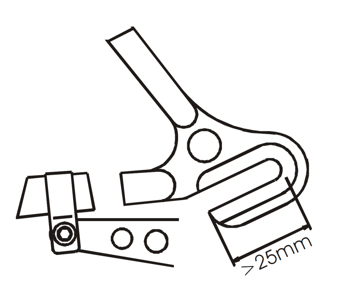
An external chain tensioner is necessary for frames where there is no other possibility to tension the chain (i.e. via an adjustable dropout, a dropout with a long slot, or an EBB). A chain tensioner is also required with dropouts where the axle has less than 25mm room for adjustment (fig. 20). This also refers to bikes with rear suspension (except models with transmission swing arms), as the chain length changes as the rear shock is activated. The tension capacity of our chain tensioner is 10 links. Rohloff chain tensioners are only suitable for 1/2" x 3/32" and 1/2" x 11/128" chains.
Use of a Disc Brake (DB)
Disc Brake versions of the Rohloff SPEEDHUB 500/14 are fitted with a special hub cap and an External Gear Mech. The flange of the hub cap has 4 tapped holes M8x0.75 onto which the brake rotor can be mounted. Only brake rotors with a special 4-bolt pattern for the Rohloff SPEEDHUB 500/14 can be used, (65mm diameter bolt diameter, inner circle diameter 52 mm).
The Rohloff AG is able to offer (at time of press) suitable brake discs for:
160/2,0mm (Art. #8282) for e.g. Magura, Tektro...
180/2,0mm (Art. #8283) for e.g. Magura, Tektro...
203/2,0mm (Art. #8284) for e.g. Magura, Tektro...
160/1,8mm (Art. #8281) for e.g. Shimano, Hayes, Formula, Avid...
180/1,8mm (Art. #8287) for e.g. Shimano, Hayes, Formula, Avid...
203/1,8mm (Art. #8286) for e.g. Shimano, Hayes, Formula, Avid...
180/2,3mm (Art. #8278)
203/2,3mm (Art. #8279)
220/2,3mm (Art. #8280)
Magura, Avid, Hope and Formula can deliver manufacturers with disc brake packages direct with the corresponding rear disc.
Contact the brake manufacturer directly for compatibility information regarding brands other than those listed above. Brake rotors with a diameter smaller than 150mm are incompatible as the caliper will collide with the SPEEDHUB shell itself.
Trailer Hitch
Package Contents
The OEM SPEEDHUB will be supplied in non-branded, OEM packaging and comes assembled with the correct axleplate, a standard splined carrier and 16 tooth sprocket (13, 15, 17, 18, 19 or 21-tooth sprocket or slim splined carrier as options).
If ordering a Gates Carbon Drive compatible SPEEDHUB, the splined sprocket carrier will be replaced with the lock-ring splined carrier (Art. #8540L). Supply of such hubs will only be supplied to manufacturers for fitting into a stiffness test approved frames. We will require a copy of the test protocol before we are able to supply these products.
The Carbon Drive sprocket will need to be secured to the lock-ring carrier, be tightening the lock-ring to 30Nm using the Rohloff Lock-Ring Tool (Art.#8518).
OEM supplied SPEEDHUBs are dispatched to EU addresses, pre-filled with SPEEDHUB all-season-oil (green flyer included in hub documentation)!
Also contained in the package are all components required for the respective hub version:
- twist shifter,
- gear cables in the required length (225 cm and/or 305 cm)
- internal cable routing
- bayonet fixing
- cable guide
- external cable box etc.
Also included in a clear plastic bag for the consumer are:
- Owners Manual,
- Warranty Card and Speedhub registration as QR Code
- Information on the Rohloff SPEEDHUB 500/14.
These last 3 items must be forwarded to the consumer when the complete bicycle is shipped.
Operating Instructions
Maintenance
In comparison to a derailleur gear system, the Rohloff SPEEDHUB 500/14 is relatively maintenance-free. The internal gearing runs encapsulated in an oil bath; it is protected by seals against dirt and moisture and is completely maintenance-free. All bearings are either sealed cartridge bearings or run also inside the hub within the oil bath. Therefore, maintenance of the Rohloff SPEEDHUB 500/14 is reduced to an annual oil change.
The indexed gearing of the Rohloff SPEEDHUB 500/14 is located directly within the hub.The cable tension has no effect on the gear shift precision.
On the Rohloff SPEEDHUB 500/14 the chain is running straight and is only driven by one large chainring. Therefore, the wear on the drive chain is fundamentally lower than with a comparable derailleur system.
Brake-in Period
All gears and coupling elements of the Rohloff SPEEDHUB 500/14 are manufactured from hardened steel and are machined to a high precision. The break-in period is approximately 1.000km due to the high wear resistance of all parts. The gears get finally smoothened out by the moving of the parts under pedaling force. The result of this process is less operational noise and a much smoother operation. The hub shell of the Rohloff SPEEDHUB 500/14 has specially constructed seals. These also take about 1.000 km to break-in; it is quite normal with a new hub, for the cranks to rotate when the bicycle is pushed, this is because the new hub seals force the sprocket to rotate with the hub. This effect recedes over time and has no influence upon riding comfort.
Operational Noise
On the Rohloff SPEEDHUB 500/14 three sets of planetary gears work in line to achieve 14 different speeds. The first two sets of planet gears produce seven gears (8th to 14th). When these seven gears are set against the third set of planet gears, then gears from 1st to 7th are produced. The third set of planetary gears rotate at extreme speeds, the highest RPM being in the 7th gear. The rotation of these planetary gears can be heard as a humming noise which is transmitted via the axle into the frame. Depending on frame type, material and other components fitted around the axle (fenders, luggage racks, kickstand etc) this noise is either more or less audible. The more the hub is ridden, the quieter these noises become. These high RPM planetary gears are not in use and the upper 7 speeds and the result is an almost silently running SPEEDHUB.
When coasting along, different freewheels may work depending on the gear selected. This too can result in different noises.
Oil Change
The Rohloff SPEEDHUB 500/14 is filled with 25ml of special gear oil (all season oil). This ensures:
- moving parts lubricated,
- steel parts protected from corrosion,
- freewheeling and gear noises subdued.
Gates Carbon Drive
The following points must be addressed and adhered to when mounting the Rohloff SPEEDHUB 500/14 together with a Gates Carbon Drive system and Rohloff lock-ring splined carrier. Failure to adhere to these points will result in partial loss of guarantee and warranty cover of the SPEEDHUB 500/14.
1. Manufacturers conditions/instructions for use
Read the Owners Manual for both Gates Carbon Drive and the Rohloff SPEEDHUB 500/14 and ensure these products are correctly implemented on the bicycle as described within the manuals:
Manual for the Gates Carbon Drive™ System used with theRohloff SPEEDHUB 500/14
2. Frame Approval
Safe operation of a SPEEDHUB using Gates Carbon Drive system is only possible if the frames reartriangle retains a minimum stiffness level. Frame manufacturers must prove frame stiffness levels on a specialist testing jig in order to receive type approval for SPEEDHUB use.
A list of manufacturers can be found at the following link:
Carbon Drive Bike Brands
Please enquire with the frame manufacturer directly should your chosen bicycle frame not be listed.
Universal Transmissions (Gates Carbon Drive EU distribution) are able to issue frame certifications on an individual basis should you still wish to use that particular frame.
Frame testing for Rohloff SPEEDHUB 500/14
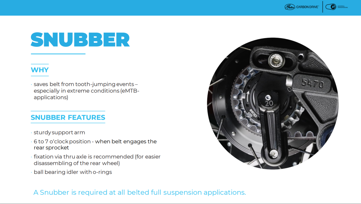
3. Use of a Snubber
The Rohloff AG insist that a Snubber is additionally mounted to the bicycle. A Snubber prevents the belt from ratcheting over sprocket teeth when belt tension is lost. Subsequently this small component greatly reduces the accident risk level. Please enquire with the frame manufacturer directly should your chosen bicycle not be fitted with a Snubber.


Suspension frame considerations
In the earliest possible stages of designing a Carbon Drive compatible rear suspension frame, there are critical engineering factors which must be taken into consideration. In general, full suspension frame designs result in some form of chain growth. Chain growth being defined as a change in the resting distance between the axis of the bottom bracket axle and the axis of the rear hub axle. Because the belt does not have the ability to stretch and the tension in the belt must remain constant, even the smallest amount of chain growth during suspension travel would be detrimental to the system integrity. Devices which compensate for drivetrain slack - such as spring loaded idlers or chain guides - are not allowed unless specifically reviewed and approved by Gates.
If a full suspension frame design which utilizes the Carbon Drive system is desired, please contact the Carbon Drive Team (CarbonDrive@Gates.com) for engineering and development assistance.
Information for Europe
Universal Transmissions GmbH
ATTN: Chris Harris
Walkmühlenstr. 194
99974 Mülhausen
Germany
chris.h@carbondrive.net
Telefon: +49 3601 888 6484
www.gatescarbondrive.com
Information for North and South America
Gates Carbon Drive
ATTN: Marc Seemann
1551 Wewatta St
Denver, CO 80202
USA
marc.seemann@gates.com
Phone: 303-744-4593